Setup
The section describes setup for the following types of sensors:
ReMoni ReCalc
Before integrating the sensors and data with our platform, all necessary configurations with ReMoni’s ReCalc platform should be accomplished. Below are provided some basic steps, but for more thorough instructions and details, please go to https://support.remoni.com/hc/en-us or get in contact with ReMoni support team.
- Make sure you have installed ReMoni sensors on all desired and identifiable locations
- Create an account within the ReCalc system at https://recalc.remoni.com
- Register and connect your Gateways
- Define your Units and register the appropriate sensors.
Important: when registering a sensor you need its sensor ID (engraved on the sensor itself) and its channel number(s). This information would later be crucial to integrate the data within our IIoT platform.
- Calibrate all sensors that need calibration to the desired Calibration Level
After all steps have been executed correctly, you can confirm this by viewing your data in the ReCalc system at https://recalc.remoni.com.
Disruptive Technologies
During the process of acquiring sensors and gateways from Disruptive Technologies, you, as a customer, should have been provided with an appropriate administrative credential for their online Studio platform. On that platform, there is a list of all your projects and sensors. Sensors can be grouped in multiple projects according to their needs. Sensor data is also available on the platform.
The following are the instructions on how to configure a DT Studio Project to export data to our IIoT Platform.
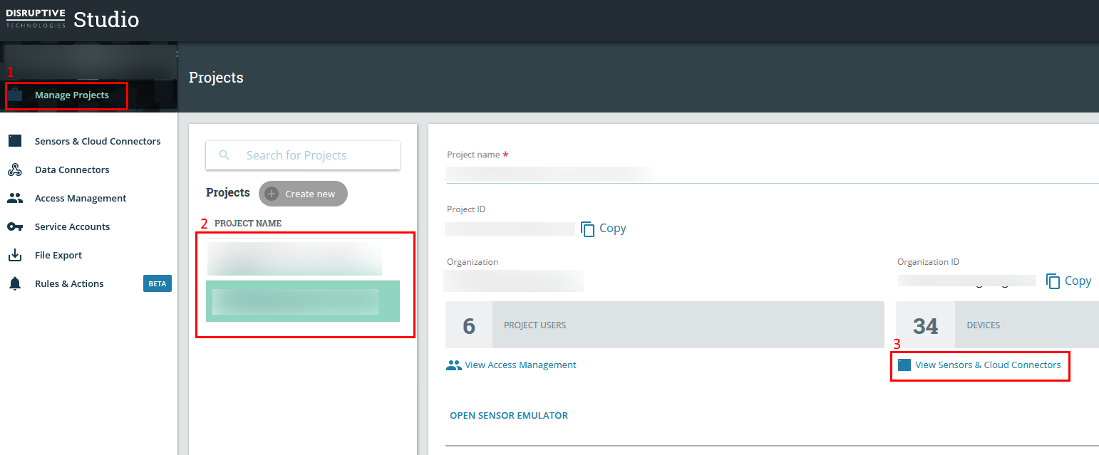
Figure 1 DT Studio configuration steps
- Go to “Manage Projects”
- Select the project from which you want to export sensor data
- Click on “View Sensors & Cloud Connectors”
At this stage, you are presented with the list of all sensors and gateways. On the left menu, select “Data connectors” and then click on the “Create new” button as shown in the figure below.
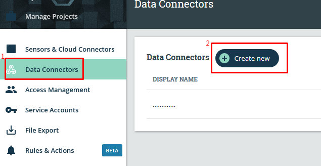
Figure 2 DT Studio data connectors
Next, you are presented with the New Data Connector dialog, where all necessary configurations must be written and saved:
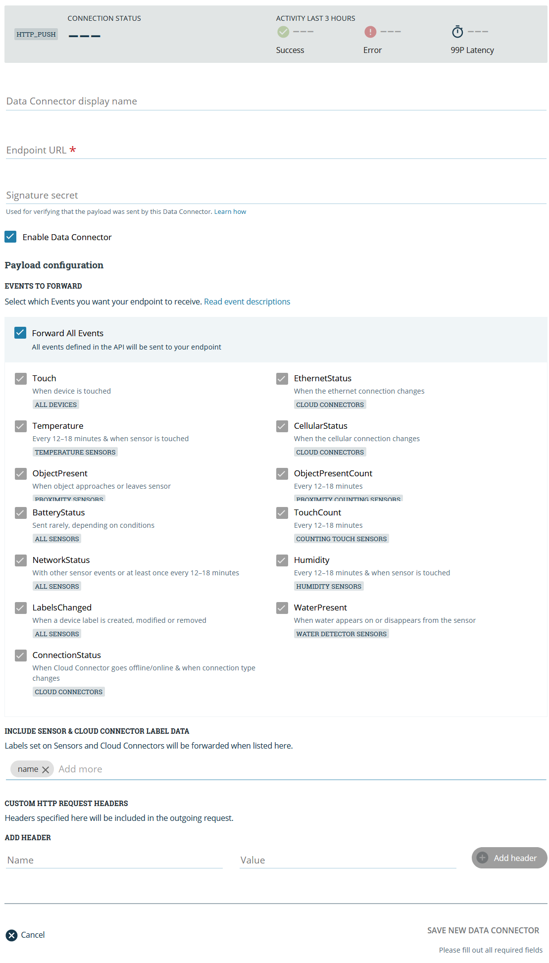
Figure 3 DT Studio new data connector
In the New Data Connector dialog enter the following data:
- Display name – just some friendly name
- Endpoint URL – this URL should be provided by the administrators of our IIoT Platform
- Enable data connector – yes
- Events to forward – select all, or just those you wish to redirect to our IIoT Platform. Currently supported events for ingestion into our IIoT Platform are: touch, temperature, proximity, battery status, connection status, cellular status
All other settings are to be left with their default values.
At the end click the “Save New Data Connector” button at the bottom.
From this point on all selected events from this project will be redirected to our IIoT Platform. On the list with all data connectors, there is a status of the data ingestion process.
NeuronSensors (El-Watch)
“Neuron” is the name of the new wireless sensor system provided by the Norwegian company El-Watch. Currently, the company provides integrational interface for both versions of their sensors system. The old one we refer to as “El-Watch (EW)”, and the new – NeuronSensors.
El-Watch
After registration of your sensors and gateways with the El-Watch online system, you have to receive an API key, which will be later required for the integration of data into our platform.
NeuronSensors
Registration details for the NeuronSensors system are provided online and are as follows:
- Step 1: Download the app EW Neuron Scan from Google Play (iOS app underway). You can also use the Neuron dashboard.
- Step 2: Log in with the username and password received from us.
- Step 3: Register the sensor(s) to your user in the app using the QR code (or type in the serial number). Give the sensor a name so you can recognize it in the app. For example ‘Temperature cold storage 2’.
- Step 4: Plug in the Neuron Gateway. If you have the Ethernet version, you will have to connect to the Internet using the enclosed Ethernet cable. If you have the GSM version, all you have to do is connect it to the power grid and it will immediately start sending data from the sensors online.
- Step 5: Place the sensors where you want them with tape, cable ties, or magnets. Under ideal circumstances, the sensors have a wireless range of about 1500 meters to the gateway, but the range is reduced by walls and other obstacles.
- Step 6: You’re up and running! Measurement data from the sensors is being delivered and is stored in our cloud. You can access it immediately in the app or online. All measurements are stored and can be analyzed in our system or downloaded and studied in more detail using other software.
- Step 7: If you want to set up alarms, the simplest way is to use the app by selecting the relevant sensor and then ‘edit sensor’ on the bottom right. Online, you log into Neuron Analytics, click on the relevant sensor in the list on the left, and then the yellow bell. You can choose to receive the alarm via SMS, e-mail, or right on your screen.
Now, it is required to configure an instance of the so called Integration. Follow these basic steps:
- Open https://neuronsensors.app and login with the already setup credentials
- Go to “Integrations” from the left menu
- Click on the “New” button to create a new integration
- From the dropdown list of types select “REST”
- Provide the following information: a descriptive name, Read access type, the system from which to read data
- When you save the new integration, an API key will be generated. Reopen the integration to see the generated API key. This API key will be later required for the integration of data into our platform.
NCD
NCD offers more than 30 types of Industrial IoT Wireless Sensors. These IoT wireless sensors are designed to interface with major cloud services like Microsoft Azure and others. These wireless sensors can be used with Local PC, MAC, Linux, or any embedded computer, they work at very low power and are designed to last for years.
Follow the instructions provided online by NCD to set up your sensors and gateways for data processing. They are briefly quoted below:
- Put the sensor into config mode. To put the sensor in configuration mode hold the CFG button down, press and release the reset button, and release the CFG button after 6 seconds
- The IoT Wireless sensor has user-defined parameters like
- Data Transmission frequency/Delay — this setting can be used to change the data transmission frequency.
- Node ID
- Network ID
- Encryption Key
- Sensor Destination Address
- Other sensor-specific parameters
- Following are a few important notes to take care of:
- The gateway should be configured to send data to Azure IoT Hub via the Device to Cloud messaging capability as shown on the figure below:
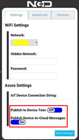
- The gateway should be configured to send data to Azure IoT Hub via the Device to Cloud messaging capability as shown on the figure below:
Figure 4 NCD required settings
- The gateway should be configured with a device connection string provided by ICB
OpenWeatherMap
OpenWeatherMap is one of the leading digital weather information providers. Our platform is focused on integrating with the current weather data provided by OpenWeatherMap. It is available for any location on Earth including over 200,000 cities! Current weather is frequently updated based on global models and data from more than 40,000 weather stations. Registration details are provided online and briefly quoted below:
- Sign up here: https://openweathermap.org/home/sign_up
- Fill in the required fields
- Done! You can find an API key on 'API keys' tab in your Personal account.
- The API key is required for further steps
Sensors Configuration
Section describes configuration in the Upkip Administration for the following types of sensors:
ReMoni
When ReMoni sensors have been configured and data is confirmed to be flowing, then the next steps should be undertaken in our IIoT platform configuration portal. There are two types of data that can be integrated: data from sensors, and alarms. Alarms are generated within the ReCalc system per sensor. Which means that for the alarms of each sensor a separate dedicated tag should be created within the platform.
- Login, go to your organization and open your tree structure of organizational elements
- Create all appropriate hierarchy levels and leaf devices to adequately represent your real facilities. This should be done in a way that logically splits different objects in your environment. Usually each ReMoni sensor channel would be registered as a separate data tag for e leaf device. Thus it would make sense that the leaf device represents the object for which ReMoni sensors measure data.
- Select the desired leaf device and proceed to create a new data tag:
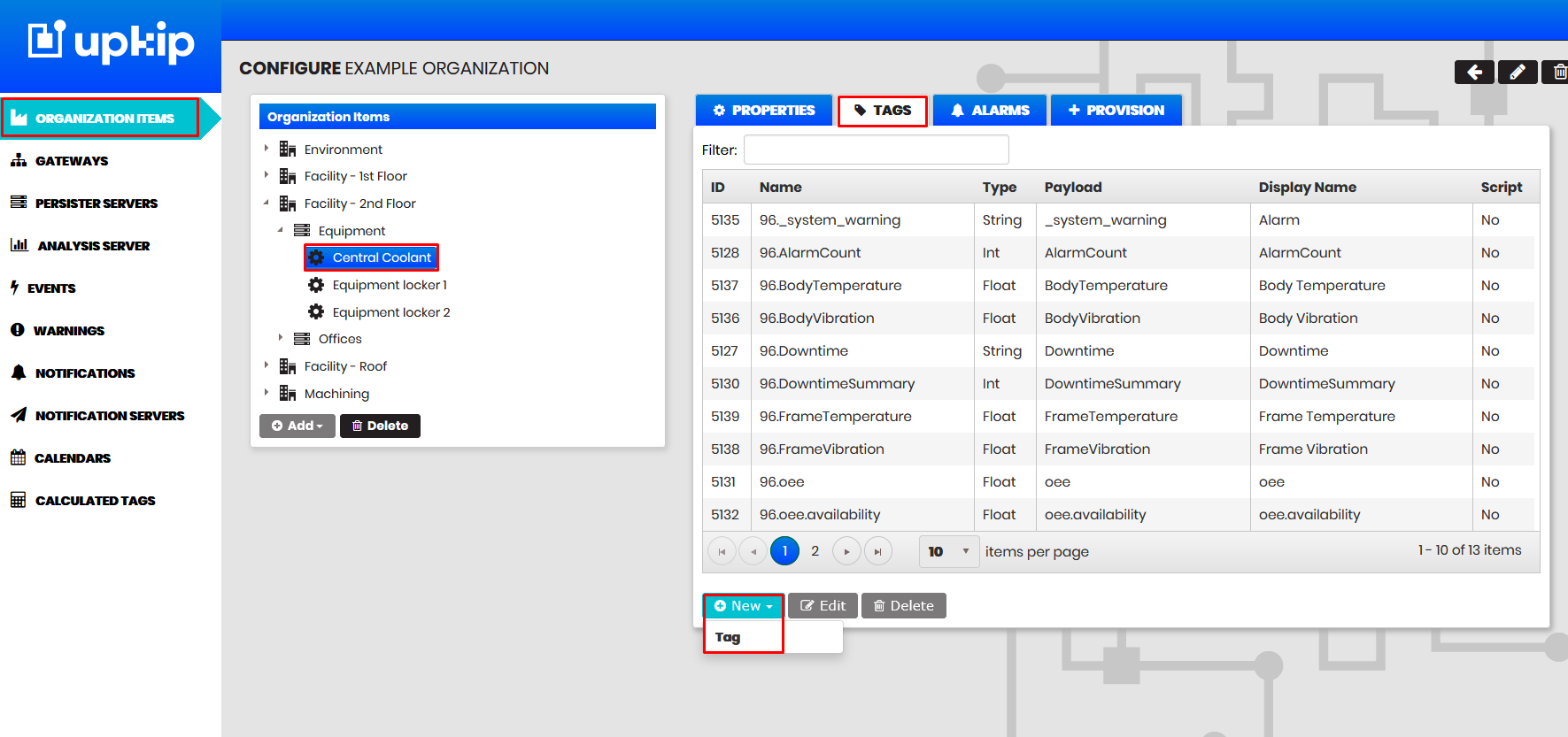
Figure 5: Select leaf device
For the new tag the following should be specified:
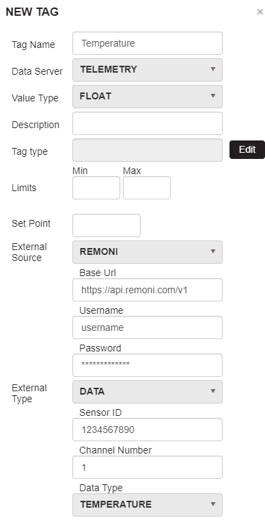
Figure 6: New data/alarm tag
- Name: a descriptive user friendly short name
- Data Server: Telemetry
- Value Type: in most cases this should be Float
- External Source: ReMoni
Important: External source properties should be configured only once and if changed, they will affect all data tags with this type of external source.
- Base URL: this is the URL of the ReMoni API interface. At the time of writing of this document the URL is https://api.remoni.com/v1
- Username and Password: these are used to securely access the API. You can enter the credentials that you use to access the ReCalc platform. However, for security reasons another user should be created and used that has the ability to only read sensor data. For details and support on this, please contact ReMoni.
- External Type: Data
*Important: this type is intended for integration of sensor measurements.
- Sensor ID: engraved on the sensor itself
- Channel Number: this is the identification of the specific measurement probe of the sensor.
- FlowMoniSpot has two temperature probes, one internal (channel 1) and one external (channel 2).
- PowerMoniSpot has three temperature probes, one internal (channel 1) and two external (channel 2 and 3).
- Please, refer to ReMoni documentation and ReCalc platform to identify the appropriate channel number.
- Data Type: this should be selected from a list of predefined measurements that all ReMoni sensors are generating. Usually, you should select the most logical (power, current, temperature, voltage, etc.). Please, refer to ReMoni documentation and ReCalc platform to identify the appropriate Data Type.
Important: please get in contact with us if your Data Type is not listed.
- Settings per sensor type:
- PowerMoniSpot offers 1 sensor channel. The data type output depends on the calibration level:
- Level 1 – Uncalibrated – Data Type is “uncalibrated-current”
- Level 2A – Manual – Data Type is “power” or “current”, according to the type of calibration
- Level 2B – Single-phase auto-calibration – Data Type is “current”
- FlowMoniSpot offers 2 sensor channels:
- Channel 1 – Internal probe – Data Type is “Temperature”
- Channel 2 – External probe – Data Type is “Temperature”*
- HeatMoniSpot offers 3 sensor channels:
- Channel 1 – Internal probe – Data Type is “Temperature”
- Channel 2 – External probe 1 – Data Type is “Temperature”*
- Channel 3 – External probe 2 – Data Type is “Temperature”*
- PowerMoniSpot offers 1 sensor channel. The data type output depends on the calibration level:
- External Type: Alarm
Important: this type is intended for integration of sensor alarms. The alarms are generated automatically by the ReCalc platform. Please, refer to ReMoni documentation for more information.
- Sensor ID: engraved on the sensor itself
- Tag Type: this is an internal to the system Type. It usually identifies the logical type of the data being stored in the tag e.g. Temperature, Power, SupplyPower, Coolant Temperature, etc. Select from the available or create a new one.
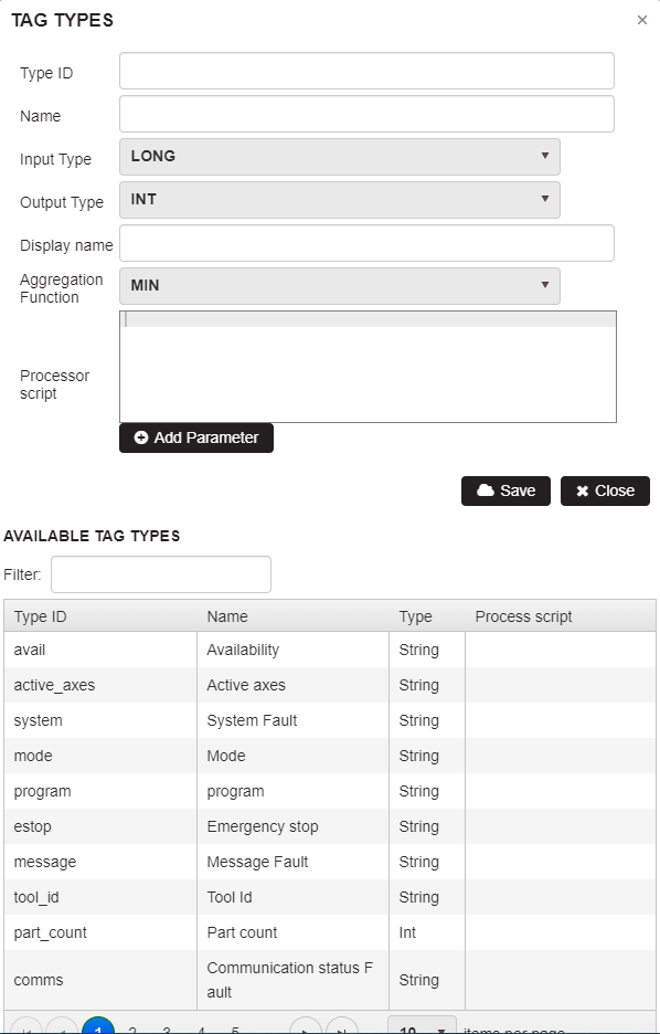
Figure 7 ReMoni tag type
On the figure above the Create/Select Tag Type dialog is presented. Under “Available Tag Types”, you can filter to select an existing type that logically describes the data that the sensor will output. The Type ID should match with the Data Type that you have selected from above. If such a Type ID is not available, then create it. Description of properties:
- Type ID – the same as the Data Type from above
- Name – descriptive user friendly short name
- Input and Output types – according to the selected Value Type from above
- Display Name – same as Type ID
- Aggregation Function and Processor script – not used
- All other properties are to be ignored
Disruptive Technologies (DT)
After all DT Studio configurations have been done, the next steps should be undertaken in our Upkip Platform configuration portal.
- Login, go to your organization and open your tree structure of organizational elements
- Create all appropriate hierarchy levels and leaf devices to adequately represent your real facilities. This should be done in a way that logically splits different objects in your environment. Usually each DT sensor would be registered as a separate data tag for e leaf device. Thus it would make sense that the leaf device represents the object for which DT sensors measure data.
- Select the desired leaf device and proceed to create a new data tag:

Figure 8 Select leaf device and create new tag
For the new tag the following should be specified:
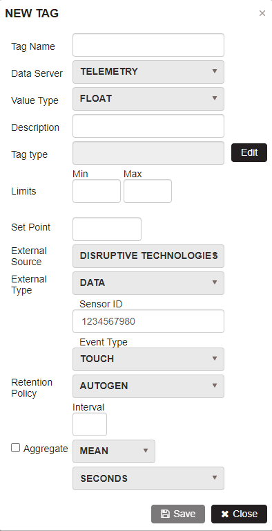
Figure 9 New DT data tag
- Name: a descriptive user friendly short name
- Data Server: Telemetry
- Value Type:
- Float for: temperature, battery status, cellular status
- String for: touch, proximity, connection status
- External Source: Disruptive Technologies
- External Type: Data
Important: this type is intended for integration of sensor measurements.
- Sensor ID: can be found in DT Studio on the sensor details page, as shown on the image below:
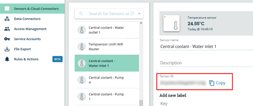
Figure 10 DT Sensor details
- Event Type: this should be selected from a list of predefined measurements of supported DT sensors. You should select one according to the type of sensor you are configuring. Please, refer to DT documentation and DT Studio platform to identify the appropriate Event Type.
Important: please get in contact with us if your Event Type is not listed.
- Tag Type: this is an internal to the system Type. It usually identifies the logical type of the data being stored in the tag e.g. Temperature, Power, Coolant Temperature, etc. Select from the available or create a new one.
Figure 11 DT Tag Type
On the figure above the Create/Select Tag Type dialog is presented. Under Available Tag Types, you can filter to select an existing type that logically describes the data that the sensor will output. The Type ID should match with the Data Type that you have selected from above. If such a Type ID is not available, then create it.
Description of properties:
- Type ID – the same as the Data Type from above
- Name – descriptive user friendly short name
- Input and Output types – according to the selected Value Type from above
- Display Name – same as Type ID
- Aggregation Function and Processor script – not used
- All other properties are to be ignored
El-Watch (EW)
After all El-Watch sensors have been configured to send data to the EW cloud, the next steps should be undertaken in our IIoT Platform configuration portal.
- Login, go to your organization and open your tree structure of organizational elements
- Create all appropriate hierarchy levels and leaf devices to adequately represent your real facilities. This should be done in a way that logically splits different objects in your environment. Usually each EW sensor sends multiple types of data. For each sensor and each of its measurements, a separate data tag should be created ant attached to a leaf device. Thus it would make sense that the leaf device represents the object for which EW sensors measure data.
- Select the desired leaf device and proceed to create a new data tag:
Figure 12 Select leaf device and create new tag
For the new tag the following should be specified:
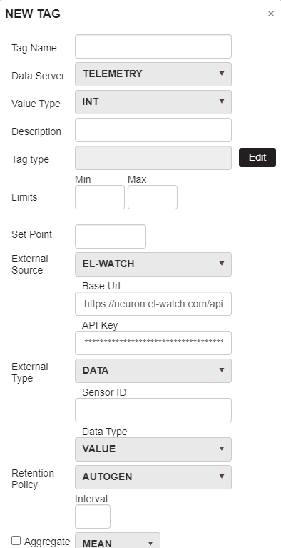
Figure 13 New EW data tag
- Name: a descriptive user friendly short name
- Data Server: Telemetry
- Value Type:
- Float for all currently supported values (rssi, value, value2)
- External Source: El-Watch
- External Type: Data
Important: this type is intended for integration of sensor measurements.
- Sensor ID: can be found in EW online platform or on the sensor itself.
- Data Type: this should be selected from a list of predefined measurements of supported EW sensors. You should select one according to the type of sensor you are configuring. Please, refer to EW documentation and platform to identify the appropriate Event Type. Choose one of the following:
- rssi – the sensor signal strength
- value – vibration measurement in [g]
- value2 – temperature measurement in [°C]
Important: please get in contact with us if your Data Type is not listed.
- Tag Type: this is an internal to the system Type. It usually identifies the logical type of the data being stored in the tag e.g. Temperature, Power, Coolant Temperature, etc. Select from the available or create a new one.
Figure 14 EW Tag Type
On the figure above the Create/Select Tag Type dialog is presented. Under Available Tag Types, you can filter to select an existing type that logically describes the data that the sensor will output. The Type ID should match with the Data Type that you have selected from above. If such a Type ID is not available, then create it.
Description of properties:
- Type ID – the same as the Data Type from above. It could also be a descriptive one, as long as it is a simple meaningful word/phrase
- Name – descriptive user friendly short name
- Input and Output types – according to the selected Value Type from above
- Display Name – same as Type ID
- Aggregation Function and Processor script – not used
- All other properties are to be ignored
NeuronSensors (NS)
After all El-Watch sensors have been configured against the new version of their platform to send data to the EW cloud, the next steps should be undertaken in our IIoT Platform configuration portal.
- Login, go to your organization and open your tree structure of organizational elements
- Create all appropriate hierarchy levels and leaf devices to adequately represent your real facilities. This should be done in a way that logically splits different objects in your environment. Usually each NS sensor sends multiple types of data. For each sensor and each of its measurements, a separate data tag should be created ant attached to a leaf device. Thus it would make sense that the leaf device represents the object for which NS sensors measure data.
- Select the desired leaf device and proceed to create a new data tag:
Figure 15 Select leaf device and create new tag
For the new tag the following should be specified:
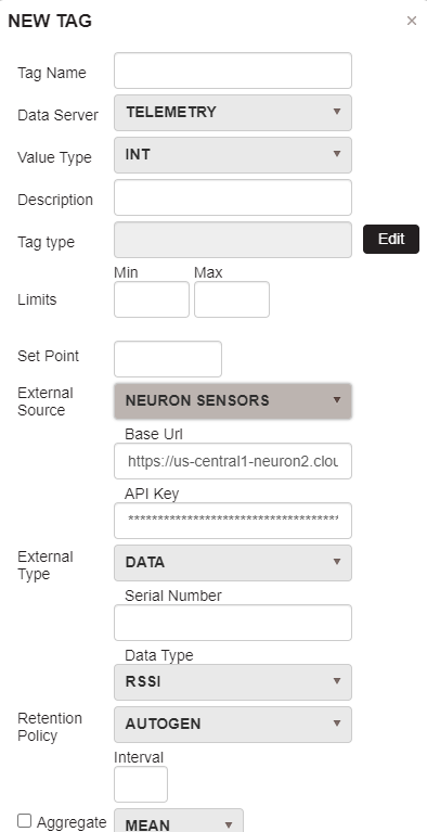
Figure 16 New NS data tag
- Name: a descriptive user friendly short name
- Data Server: Telemetry
- Value Type:
- Float for all currently supported values (rssi, values[0], values[1])
- External Source: Neuron Sensors
- External Type: Data
Important: this type is intended for integration of sensor measurements.
- Serial Number: can be found in NS online platform or on the sensor itself.
- Data Type: this should be selected from a list of predefined measurements of supported NS sensors. You should select one according to the type of sensor you are configuring. Please, refer to NS documentation and platform to identify the appropriate Event Type. Choose one of the following:
- rssi – the sensor signal strength
- values[0] – vibration measurement in [g]
- values-[1] – temperature measurement in [°C]
Important: please get in contact with us if your Data Type is not listed.
- Tag Type: this is an internal to the system Type. It usually identifies the logical type of the data being stored in the tag e.g. Temperature, Power, Coolant Temperature, etc. Select from the available or create a new one.
Figure 17 NS Tag Type
On the figure above the Create/Select Tag Type dialog is presented. Under “Available Tag Types”, you can filter to select an existing type that logically describes the data that the sensor will output. The Type ID should match with the Data Type that you have selected from above. If such a Type ID is not available, then create it.
Description of properties:
- Type ID – the same as the Data Type from above. It could also be a descriptive one, as long as it is a simple meaningful word/phrase
- Name – descriptive user friendly short name
- Input and Output types – according to the selected Value Type from above
- Display Name – same as Type ID
- Aggregation Function and Processor script – not used
- All other properties are to be ignored
NCD
After all NCD sensors have been configured to send data to our internal Azure IoT Hub, the next steps should be undertaken in our IIoT Platform configuration portal.
- Login, go to your organization and open your tree structure of organizational elements
- Create all appropriate hierarchy levels and leaf devices to adequately represent your real facilities. This should be done in a way that logically splits different objects in your environment. Usually each NCD sensor, according to its type, sends multiple types of data. For each sensor and each of its measurements, a separate data tag should be created ant attached to a leaf device. Thus it would make sense that the leaf device represents the object for which NCD sensors measure data.
- Select the desired leaf device and proceed to create a new data tag:
Figure 18 Select leaf device and create new tag
For the new tag the following should be specified:
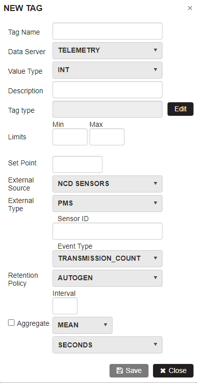
Figure 19 New NCD data tag
- Name: a descriptive user friendly short name
- Data Server: Telemetry
- Value Type:
- Float for all currently supported values
- External Source: Neuron Sensors
- External Type: Data
Important: this type is intended for integration of sensor measurements.
- Sensor ID: can be found on the NCD sensor itself.
- Data Type: this should be selected from a list of predefined measurements of supported NCD sensors. You should select one according to the type of sensor you are configuring. Please, refer to NCD documentation and platform to identify the appropriate Event Type. Choose one of the following:
- transmission_count
- battery_level
- rssi
- rms_x
- rms_y
- rms_z
- max_x
- max_y
- max_z
- min_x
- min_y
- min_z
- Vibration_Celsius
- Thermocouple_Celsius
- Current
Important: please get in contact with us if your Data Type is not listed.
- Tag Type: this is an internal to the system Type. It usually identifies the logical type of the data being stored in the tag e.g. Temperature, Power, Coolant Temperature, etc. Select from the available or create a new one.
Figure 20 NCD Tag Type
On the figure above the Create/Select Tag Type dialog is presented. Under “Available Tag Types”, you can filter to select an existing type that logically describes the data that the sensor will output. The Type ID should match with the Data Type that you have selected from above. If such a Type ID is not available, then create it. Description of properties:
- Type ID – the same as the Data Type from above. It could also be a descriptive one, as long as it is a simple meaningful word/phrase
- Name – descriptive user friendly short name
- Input and Output types – according to the selected Value Type from above
- Display Name – same as Type ID
- Aggregation Function and Processor script – not used
- All other properties are to be ignored
OpenWeatherMap (OWM)
After a successful registration has been made on the OWM site, the next steps should be undertaken in our IIoT Platform configuration portal.
- Login, go to your organization and open your tree structure of organizational elements
- Create all appropriate hierarchy levels and leaf devices to adequately represent your real facilities. This should be done in a way that logically splits different objects in your environment. Usually the weather data is defined as a fictive device under a node called Environment/CityName.
- Select the desired leaf device and proceed to create a new data tag:
Figure 21 Select leaf device and create new tag
For the new tag the following should be specified:
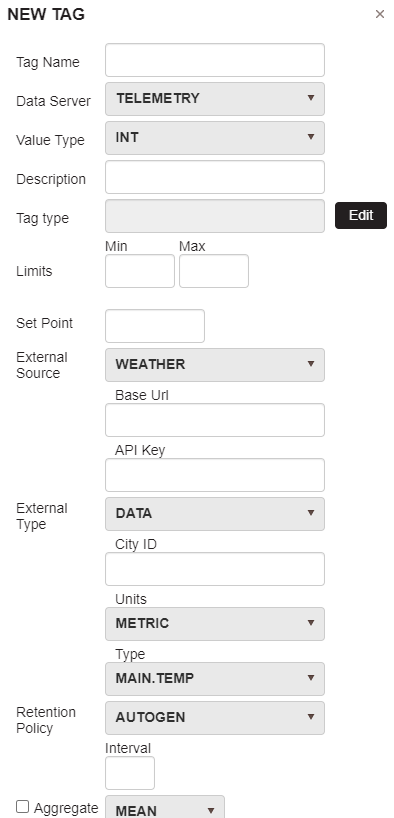
Figure 22 New OWM data tag
- Name: a descriptive user friendly short name
- Data Server: Telemetry
- Value Type:
- Float or Integer for all currently supported values
- External Source: Weather
- External Type: Data
Important: this type is intended for integration of sensor measurements.
- City ID: can be found in OWM online platform
- Units: metric/imperial/default
- Type: this should be selected from a list of predefined measurements of supported OWM readings. You should select one according to the type of data you are configuring. Please, refer to OWM documentation and platform to identify the appropriate Type. Choose one of the following
- main.temp
- main.feels_like
- main.temp_min
- main.temp_max
- main.pressure
- main.humidity
- main.sea_level
- main.grnd_level
- wind.speed
- wind.deg
- wind.gust
- clouds.all
- rain.1h
- rain.3h
- snow.1h
- snow.3h
Important: please get in contact with us if your Type is not listed.
- Tag Type: this is an internal to the system Type. It usually identifies the logical type of the data being stored in the tag e.g. Temperature, Power, Coolant Temperature, etc. Select from the available or create a new one.
Figure 23 OWM Tag Type
On the figure above the Create/Select Tag Type dialog is presented. Under “Available Tag Types”, you can filter to select an existing type that logically describes the data that the sensor will output. The Type ID should match with the Data Type that you have selected from above. If such a Type ID is not available, then create it.
Description of properties:
- Type ID – the same as the Data Type from above. It could also be a descriptive one, as long as it is a simple meaningful word/phrase
- Name – descriptive user friendly short name
- Input and Output types – according to the selected Value Type from above
- Display Name – same as Type ID
- Aggregation Function and Processor script – not used
- All other properties are to be ignored