Automatic Optimizer
Purpose: Automatically optimize the energy consumption of HVAC equipment that works together with machines in shared areas to keep the temperature within certain limits.
The HVAC equipment consists of heating, ventilation, humidity, cooling, or air-conditioning equipment.
The optimizer sents commands to the devices according to certain rules to turn them on or off and maintain the temperature within certain limits.
A calculated tags are used to determine the rules for turning devices on or off. When the temperature from the sennsors meets the rules, the event is triggered and the device control command is sent to the HVAC device.
Creating an automatic optimizer goes through the following steps:
Precondition: Machines and HVAC devices must be configured in the organization structure.
Select the Organization menu. Select the machine with a configured tag associated with the external sensor. From the Tags list select the tag.
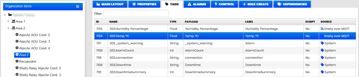
Figure 1: Machine tags list
Click the Update button to view the tag configuration.
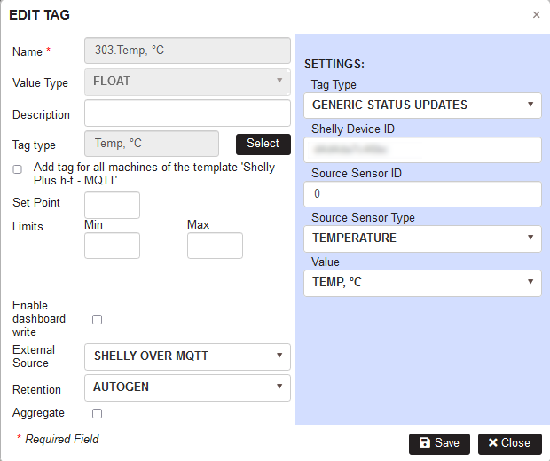
Figure 2: Machine tag configuration associated with an external sensor
To start the optimizer configuration, select the Optimizer menu.
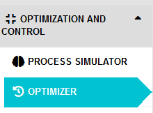
Figure 3: Optimizer menu
- The list of configured optimizers opens.
Create Automatic Optimizer
Click the Add button to launch the Optimizer Configuration Wizard.
- The first step Mode selection opens.
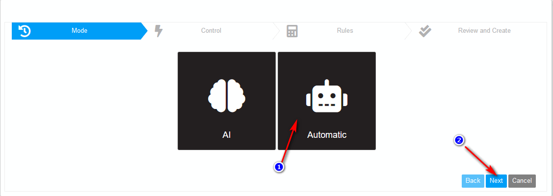
Figure 4: Optimizer wizard - step 1 - Mode selection
Click the button Automatic for automatic optimization and then click the Next button.
- Step 1 Control of the wizard opens.
Step1: Control
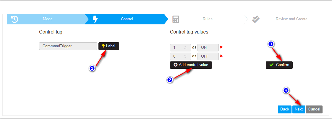
Figure 5: Optimizer wizard - step 2 - Control
Click on the Label button and select tag type from the available ones.
Click on the button Add control value and define the control tag value and their alias.
Click on the Confirm button.
- Events are created for each control tag value.
For details on how to create and view events go to Events.
The event is fired only when the tag changes its value to the one set in the event configuration – ON (1) or OFF (0).
Click the Next button.
- Step 2 Rules of the wizard opens.
Step2: Rules
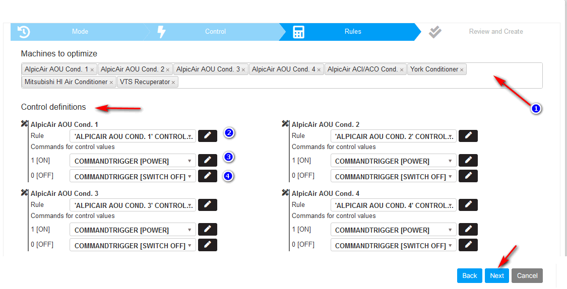
Figure 6: Optimizer wizard - step 3 – Rules
Click the filter (1) to select machines to optimize. It is possible to select multiple machines.
- Control definitions are created for each machine in the filter.
Click on the rule edit button for the first machine (2).
- Calculated Tag definition with the rule expression is opened.
For details on creating calculated tags go to Calculated Tags.
The calculated tag definition allows parameters to be defined with values used in the expression.
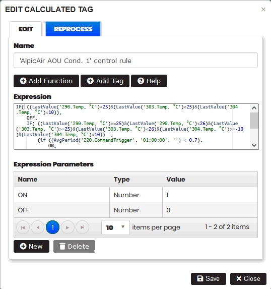
Figure 7: Optimizer - calculated tag with expression rule for machine
Click on the edit button (3) for device command.
- A Control command form with payload for control value 1 (ON) is opened.
Click on the edit button (4) for device command.
- A Control command form with payload for control value 0 (OFF) is opened.
A Payload command is a specific JSON submitted to the machine.
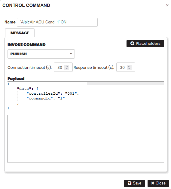
Figure 8: Device control command
For details on creating device control commands go to Device Control.
When the rule expression for the calculated tag returns 0 (ON) or 1 (OFF) to the selected control tag, the corresponding event is fired. The appropriate device control command is then sent to the device to turn them on or off.
Click the Next button.
- Step 3 Review and Create of the wizard opens.
Step3: Review and Create
The user makes the final review of the created automatic optimizer.
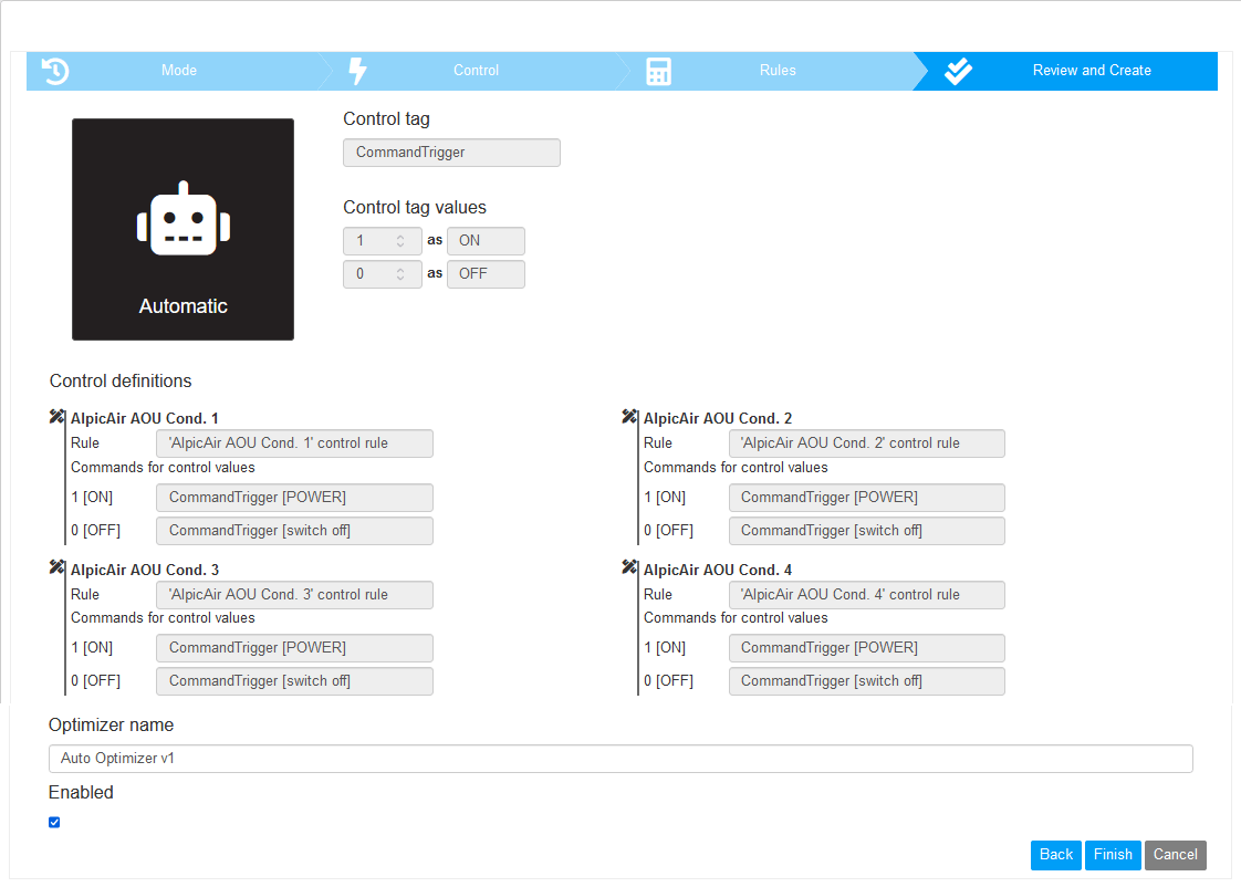
Figure 9: Optimizer - step 4 - review and create
Enter the optimizer name. Check option Enabled to enable the optimizer.
Click the button Finish.
- The created optimizer appears in the list.
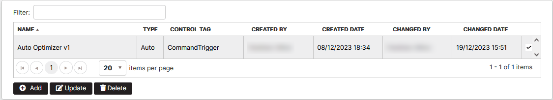
Figure 10: Optimizer list
The optimizer can be updated by selecting from the list and clicking the Update button.
The optimizer can be deleted by selecting from the list and clicking the Delete button.
Process Simulator
Purpose: The process simulator is a mechanism for describing the linear regression model of the environment.
A regression model provides a function that describes the relationship between one or more independent variables and a dependent or target variable.
Regression is widely used in Machine Learning to predict the behavior of one variable depending upon the value of another variable.
The regression model is used later in the Artificial Intelligence Optimizer. It works as an autonomous system that makes decisions without human intervention.
In practice, with the help of the process simulator and the AI optimizer, a group of air conditioners turns on or off autonomously, keeping the temperature in the room within certain limits, minimizing the energy used.
Creating a process simulator goes through the following steps:
- Step1: Characteristics
- Step2: Output
- Step3: Target
- Step4: Settings
- Step5: Preview and Train
- Step6: Evaluate and Save
Create process simulator
Purpose: By creating the process simulator, we make a regression model of the environment.
Precondition: Log in to the Upkip Administration module.
Expand the menu Optimization and control. Click the menu Process Simulator.
- The Process Simulator page opens.
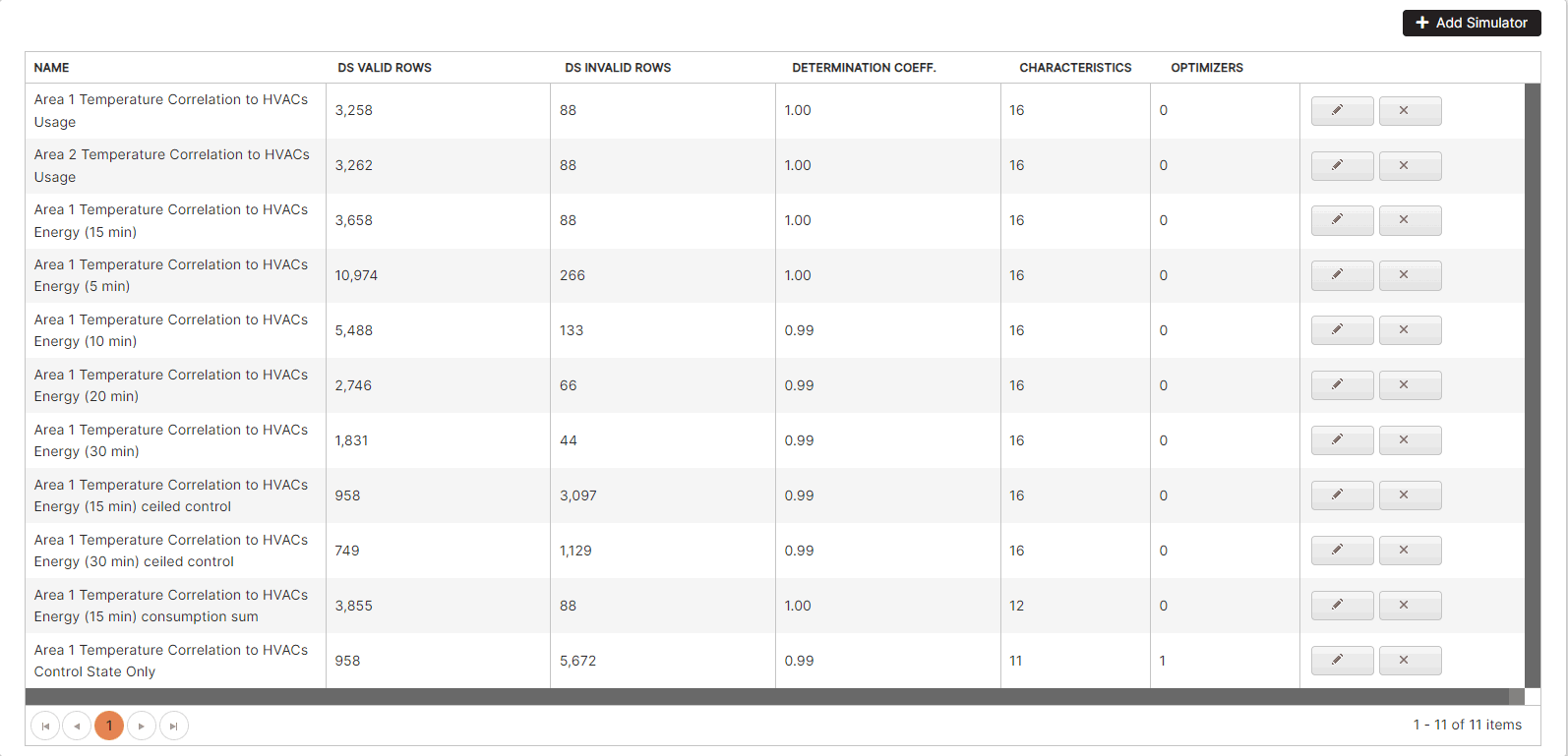
Figure 11: Process simulators list
A 6-steps wizard is used to define a process simulator.
Click the Add Simulator button.
- The wizard for creating a new process simulator opens. The first step is active.
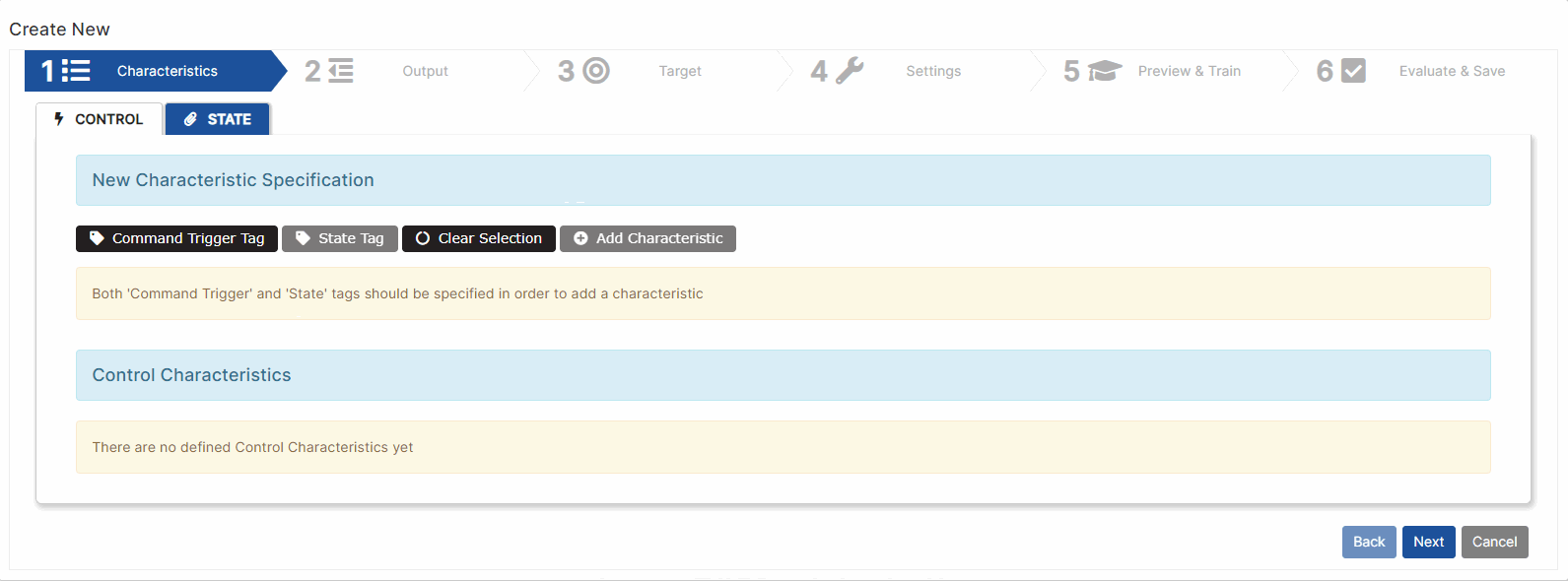
Figure 12: Create new process simulator
Step 1: Process Simulator Characteristics
In this step, characteristics are defined, which are of two types: control and state characteristics.
For example, there are sensors for measuring indoor temperatures in zone 1, zone 2 and outdoor temperature. Depending on the temperature in zone 1, zone 2 and the outside temperature, we want to turn on or off different air conditioners to keep the temperature in zone 1 within certain limits.
Add Control characteristics
Control characteristics are the state of the air conditioners (on or off). They are described in two tags: command trigger tag (Int value) and state tag (Int or Float value).

Figure 13: Characteristics - define control characteristics
The Control tab is selected.
Click the button Command Trigger Tag. From the organization tree, click on the machine and select a machine tag of type Int.
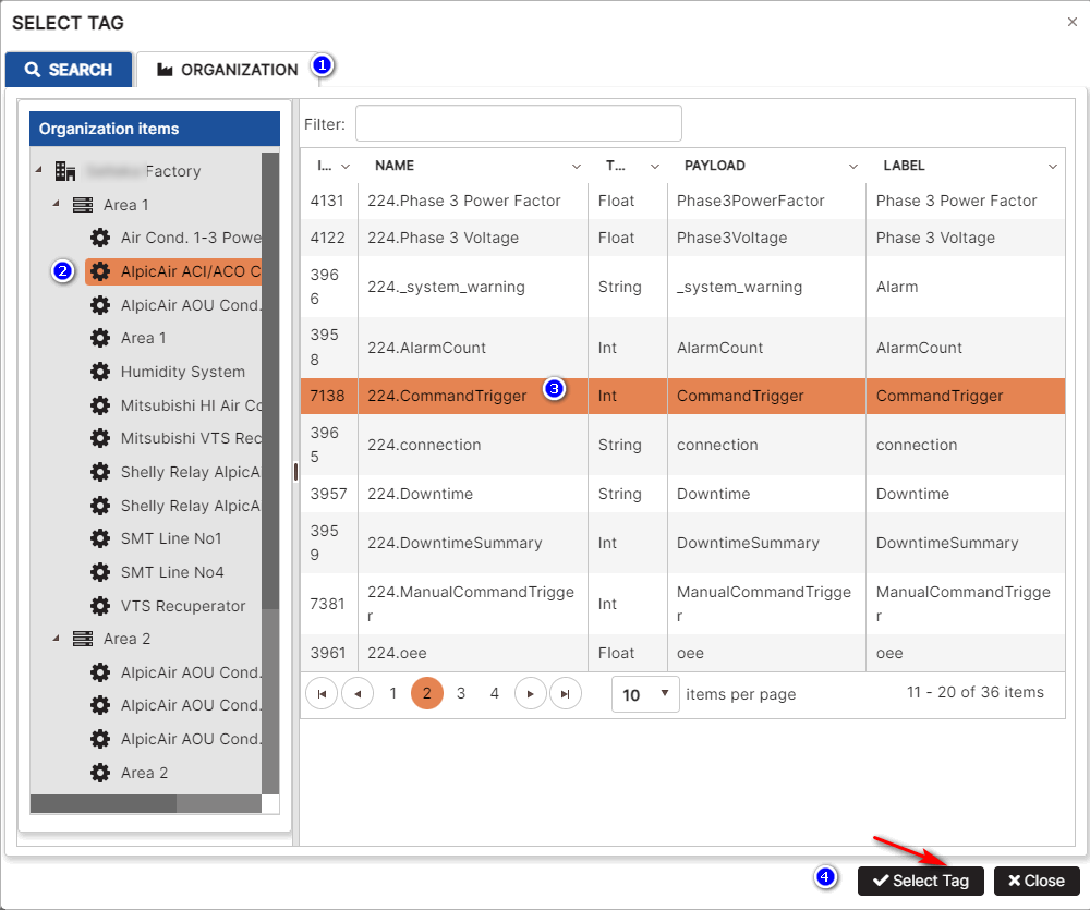
Figure 14: Select machine tag as control tag
Click the button State Tag. From the organization tree, click on the machine and select a machine tag of type Int or Float.
- A table with Device Name, Device ID, Control Tag, and State Tag appears.
- For some devices, control tag and state tag are the same tag.
- For other devices, command trigger tag and state tag are different tags.
Click the button Add Characteristic.
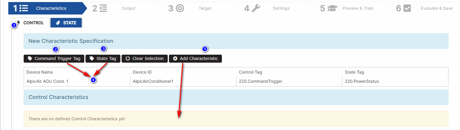
Figure 15: Add the control characteristic
- The control characteristic is added in the section Control Characteristics.
Repeat the steps for all control characteristics.
- A list of control characteristics is created.
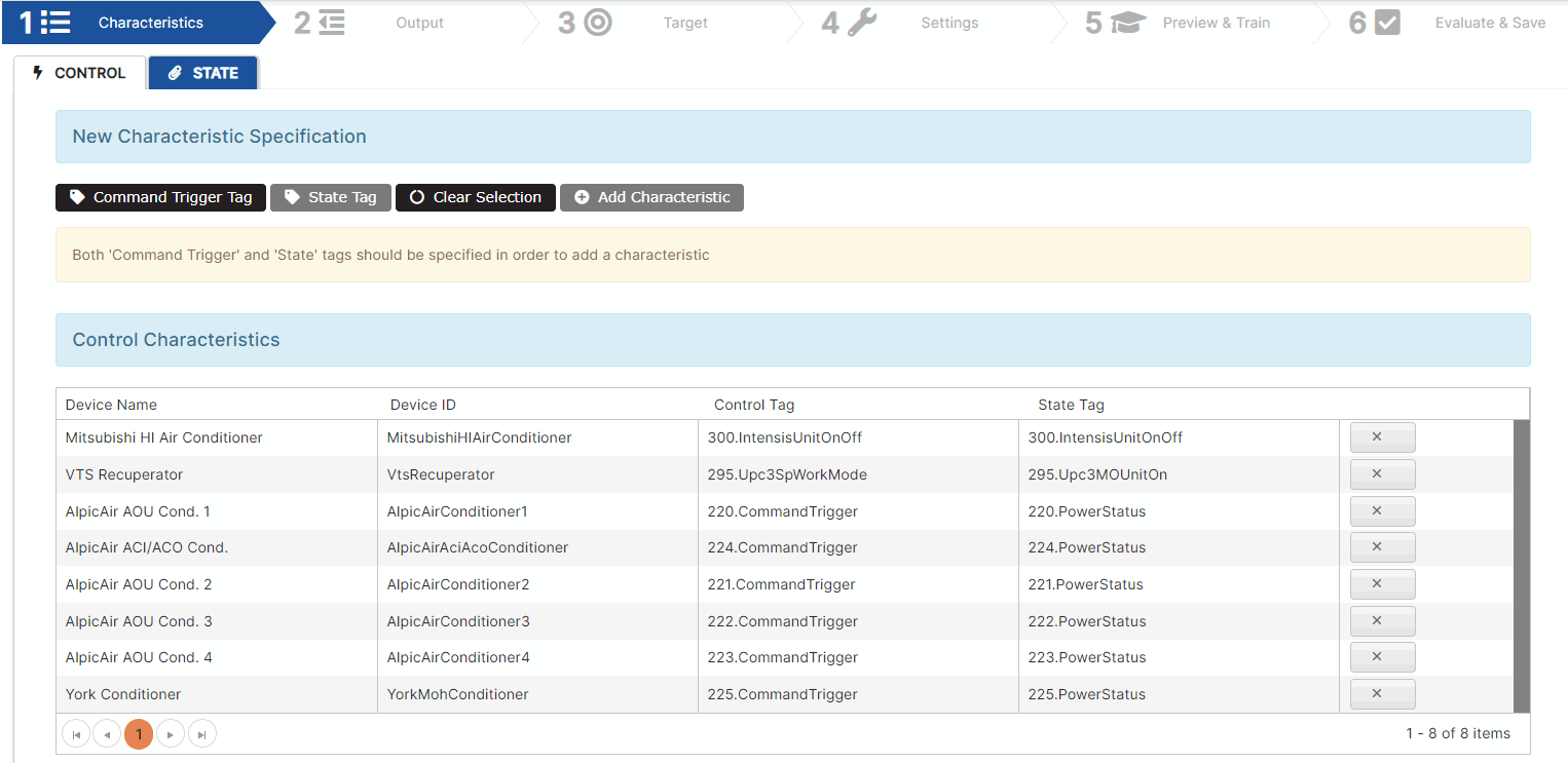
Figure 16: Process simulator - control characteristics
For regression analysis, the optimizer uses a state tag of the control characteristics (for example, PowerStatus tag).
In the process simulator there should be at least one control characteristic.
Add State Characteristics
Click the tab State.
Repeat the steps to select state tags associated with the devices or rooms. Click the Add Characteristic button to add them to the State Characteristic list.
State characteristics describe some momentary state of the environment. They are not controlled. Each state characteristic has a one state tag.
For example, select tags with zone 1 temperature, zone 2 temperature, and outside temperature.
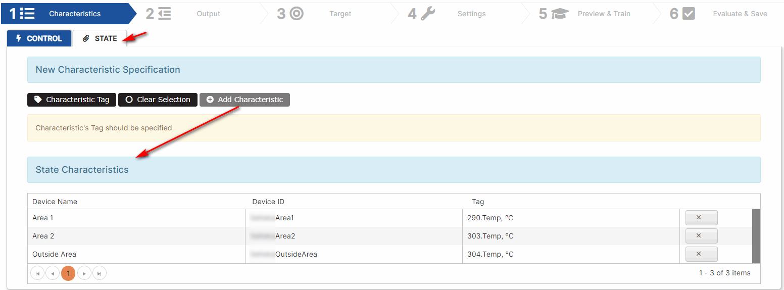
Figure 17: Process simulator - state characteristics
Click the Next button.
- The Output step of the wizard opens.
Step 2: Process Simulator Output (optional)
Output values are constant (momentary) values associated with the characteristics, regardless of whether it is a control or a state characteristic.
Output values are calculated for the configured control characteristics. The values are written in the selected tag.
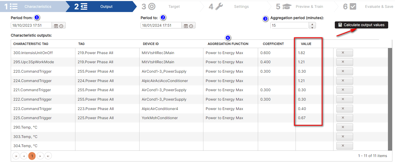
Figure 18: Process simulator - output values
The output value is calculated for the selected period (e.g. 3Months).
Each period is divided into aggregation intervals of selected minutes (e.g. 15 minutes)
For each characteristic:
- Click on the Tag cell and select a tag for the value.
- From the Aggregation Function drop-down menu, select a function. Available functions are Min, Max, Average, Power to Energy Min, Power to Energy Max, Power to Energy Average.
- The aggregation function is applied to the values of each interval.
The characteristic output per period is a single value that is a constant. A coefficient can be added to the final value calculation.
Click the button Calculate output values.
- The output values for the control characteristics are calculated.
Click the Next button.
- The Target step of the wizard opens.
Step 3: Process Simulator Target
In the step is selected the target for linear regression. It is a dependent variable.
Click the button Target Tag. Select from the organization structure a tag for the target values.
For example, select a tag for the temperature of zone1 to be controlled.
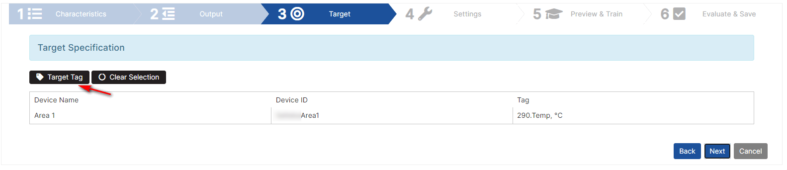
Figure 19: Process simulator - select target
Click the Next button.
- The Settings step of the wizard opens.
Step 4: Process Simulator Settings
Settings determine how the data will be loaded to run the regression model.
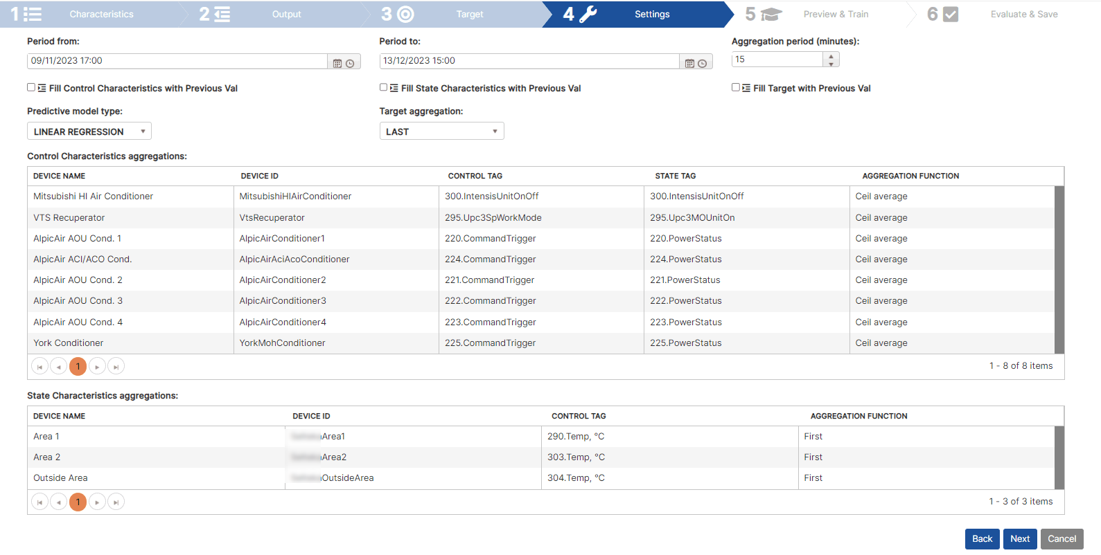
Figure 20: Process simulator - settings
Set the following data:
- Period From and Period To - define the data loading period.
- Set the aggregation period in minutes (e.g. 15 minutes)
- Select or not the checkboxes “Fill control characteristics with previous val”, “Fill state characteristics with previous val”, “Fill target with previous val”.
- Select predictive model type – linear regression.
- Select the target aggregation function from the drop-down list: Min, Max, Average, Count, Sum, Cell average, First, Last, Power to Energy, Floor average, and Round average. This function will be used for target calculation.
- For each control characteristic, select an aggregation function. For example, Cell average.
- For each state characteristic, select an aggregation function. For example, First.
Click the Next button.
- The Review & Train step of the wizard opens.
Step 5: Process Simulator Preview & Train
Based on the Settings, a data set (valid and invalid values) is loaded.
Click the button Load dataset.
- Valid data is loaded for all characteristics and target (e.g. 958 rows).
The table shows a preview of the data (first 20 rows).
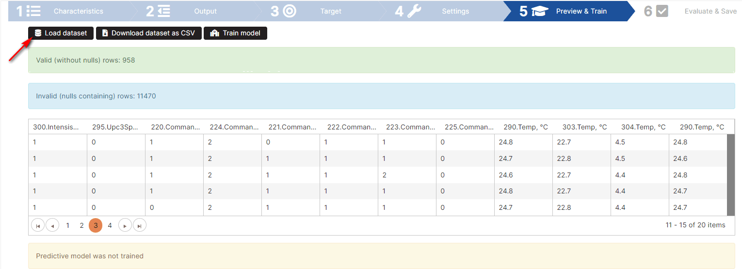
Figure 21: Process simulator - loaded data set
To get all data in a csv file, click the Download dataset as CSV button.
To train model in regression analysis means to determine the coefficients in the model.
Click the button Train model.
- The coefficients for the regression model are calculated.
- For all characteristics, coefficients are calculated, shown in the column Score (Coefficient).
- The table with columns Device Name, Device ID, Tag, and Score (Coefficient) is displayed. The rows for each characteristic and their coefficient are displayed.
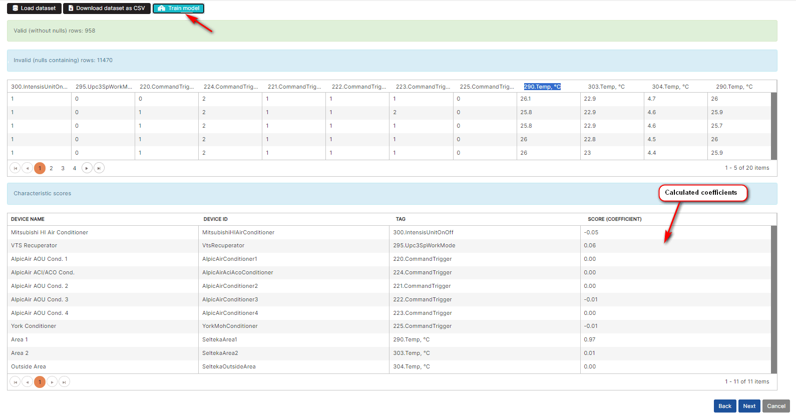
Figure 22: Process simulator - regression model coefficients
Coefficients for characteristics can be positive or negative.
The characteristics with higher values (positive) for corresponding coefficients have more weight in the regression model.
A positive coefficient indicates that as the value of the independent variable increases, the mean of the dependent variable (target) also tends to increase.
A negative coefficient suggests that as the independent variable decreases, the dependent variable (target) tends to decrease.
Click the Next button.
- The Evaluate & Save step of the wizard opens.
Step 6: Process Simulator Evaluate & Save
The Coefficient of determination is calculated in the step.
Click the button Calculate Coefficient of Determination.
- The value of coefficient of determination is displayed.
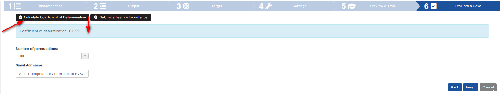
Figure 23: Process simulator - evaluate coefficient of determination
The coefficient of determination means how good the model is. The higher the coefficient, the better model.
For example, the coefficient of determination is 0.99.
Set the number of permutations, for example 1000. Click the button Calculate Feature importance.
- The result table shows for each characteristic score (coefficient) and importance value. It shows for each characteristic how important it is to the environment regression model.
For example, the Area1 characteristic is the most important.
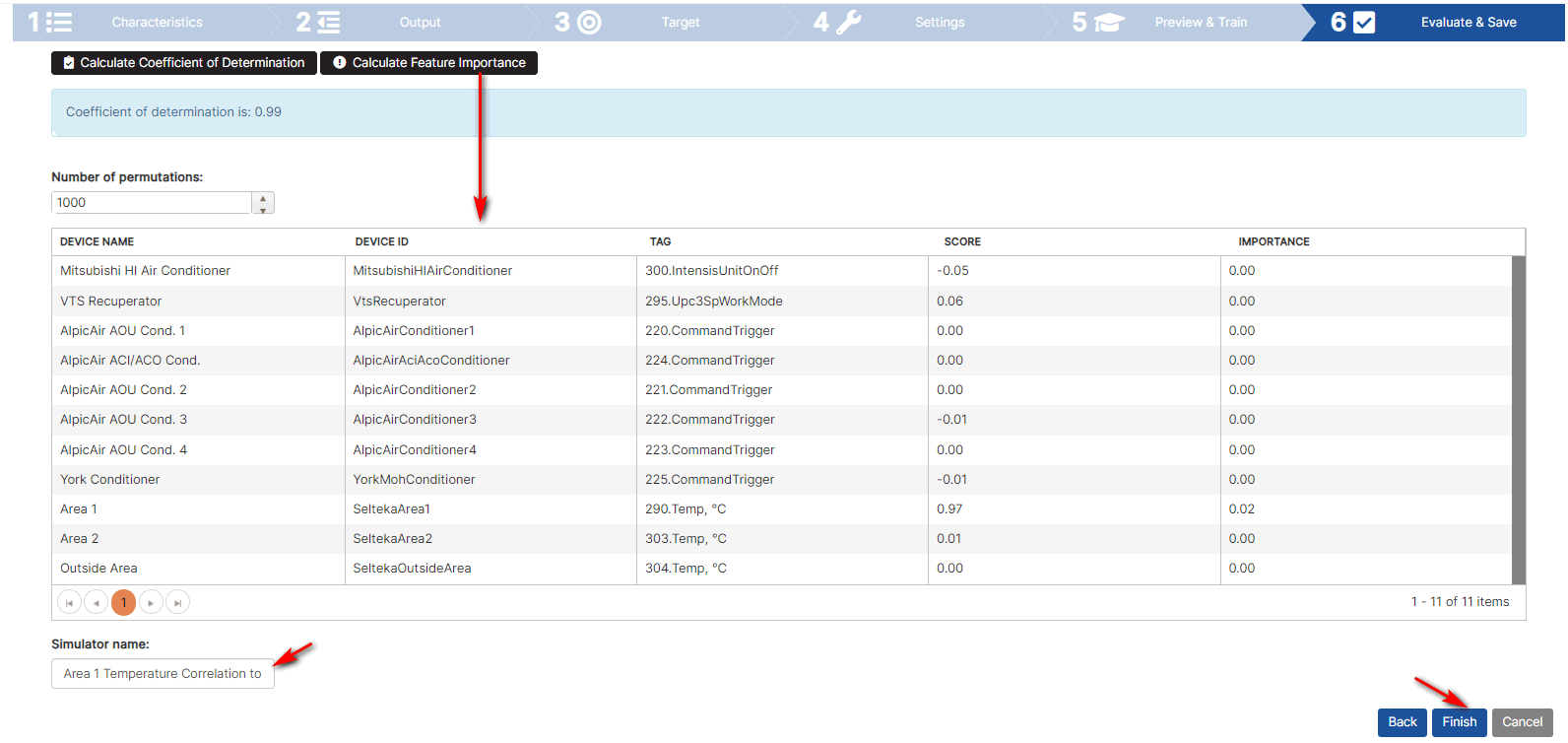
Figure 24: Process simulator - characteristics importance
Enter the simulator name and click Finish.
- If the simulator is not associated with the optimizer it is updated.
- If the simulator is associated with optimizer only closes the simulator.
Artificial Intelligence Optimizer
Purpose: The Artificial Intelligence (AI) Optimizer works as an autonomous system with a described process simulator (environment description for the regression analysis model).
At a configured interval, it calculates by linear regression using Google OR-Tools for optimization, variables, constants, defined constraints, and objectives and writes values to the control tags.
For each control tag, a device control command is developed, which is triggered by the recorded values, and turns the air conditioners on or off.
For example, the goal of the AI Optimizer is to have a group of air conditioners turn on or off autonomously, keeping the temperature in the room within certain limits, with minimal energy consumption.
Creating an AI optimizer goes through the following steps:
- Select AI Optimizer type
- Step1: Settings
- Step2: Variables and Constants
- Step3: Constraints
- Step4: Objectives
Create AI Optimizer
Precondition: Log in to the Upkip Administration module.
Expand the menu Optimization and control. Click the menu Optimizer.
- The Optimizer page opens.
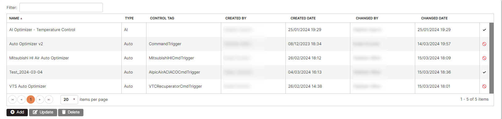
Figure 25: Optimizers list
Click the Add button. Click the AI (Artificial Intelligence) optimizer button to select the optimizer type.
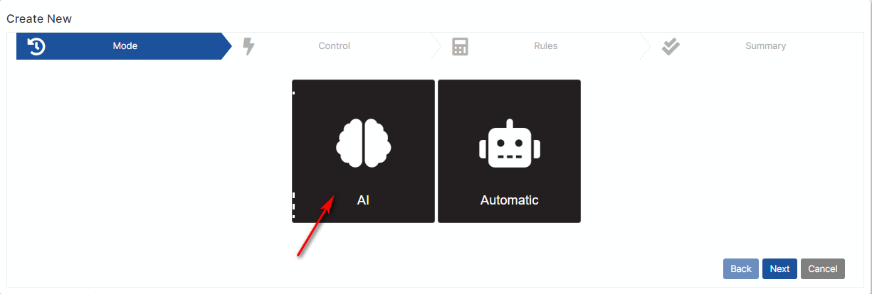
Figure 26: Optimizer - select AI optimizer mode
Click the Next button.
- Step 1 Settings of AI optimizer opens.
Step 1: AI Optimizer Settings
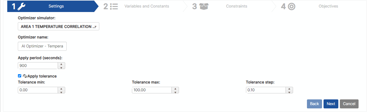
Figure 27: AI optimizer - settings
Select the process simulator from the optimizer simulator drop-down list. To see how the process simulator is defined, click Create process simulator.
Set the Apply period (seconds). This is the period in which the optimizer works.
Set Min, Max, and Step tolerance and choose whether to apply. Tolerance refers to target constraints.
Click the Next button.
- Step 2 Variables and Constants of AI optimizer opens.
Step 2: AI Optimizer Variables and Constants
In the step are defined variables and constants.
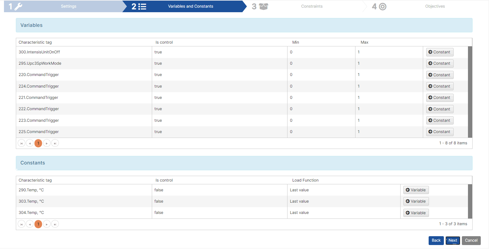
Figure 28: AI optimizer - variables and constants
All control characteristics from the defined process simulator are listed as variables.
All state characteristics from the defined process simulator are listed as constants.
To see how control and state characteristics are defined in the process simulator, click Step 1: Process Simulator Characteristics
The Variables table has a Constant button to convert a variable to a constant. Conversely, there is a Variable button in the Constants table to convert a constant to a variable.
There must be at least one variable. Constants are optional.
A variable is a characteristic definition for which the optimizer must calculate an optimal value.
When a variable is defined, it has a minimum and maximum value. The optimizer calculates the optimal value between min and max.
For the air conditioners example, they contains min 0 and max 1 (states off and on).
A constant contains a value that is calculated once by the optimizer. This is the last value.
Click the Next button.
- Step 3 Constraints of AI optimizer opens.
Step 3: AI Optimizer Constraints
Constraints are displayed in the expandable panels.
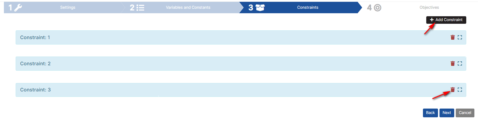
Figure 29: AI optimizer – Constraints
Click the Add Constraint button.
- A new panel Constraint is added to the page.
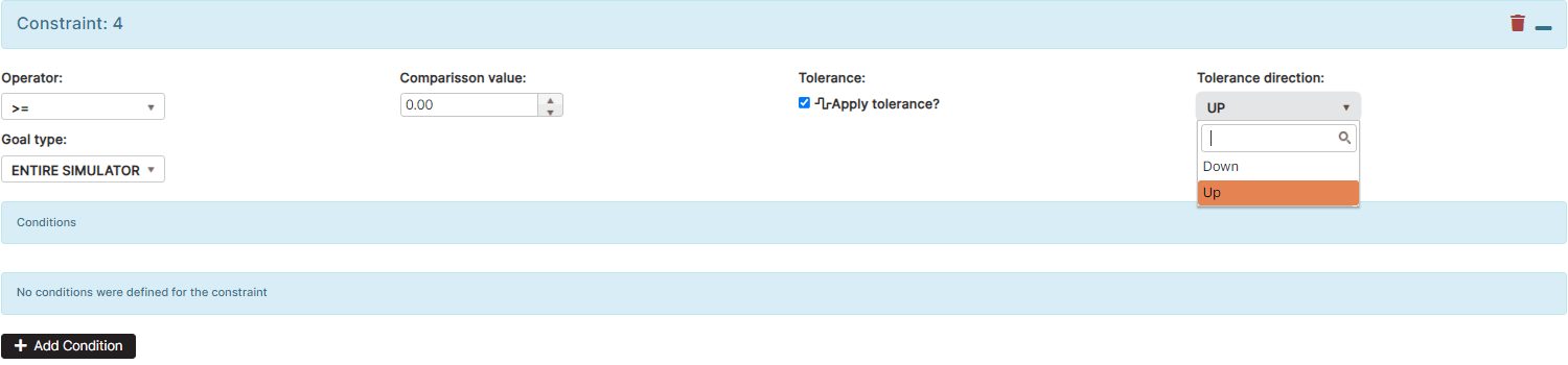
Figure 30: AI optimizer - new constraint
To remove the constraint, click the remove button icon associated with the constraint.
Linear programming has constraints and objectives. Each constraint is an inequality.
Each constraint has the following parameters:
- Operator – logical operator.
- Comparison value – used in the operator.
- Tolerance – if apply the tolerance.
- Tolerance direction – select Up or Down direction.
- Goal type – Еntire simulator or custom clauses.
In the constraint section is possible to add conditions.
Constraint 1
Expand the constraint panel 1.
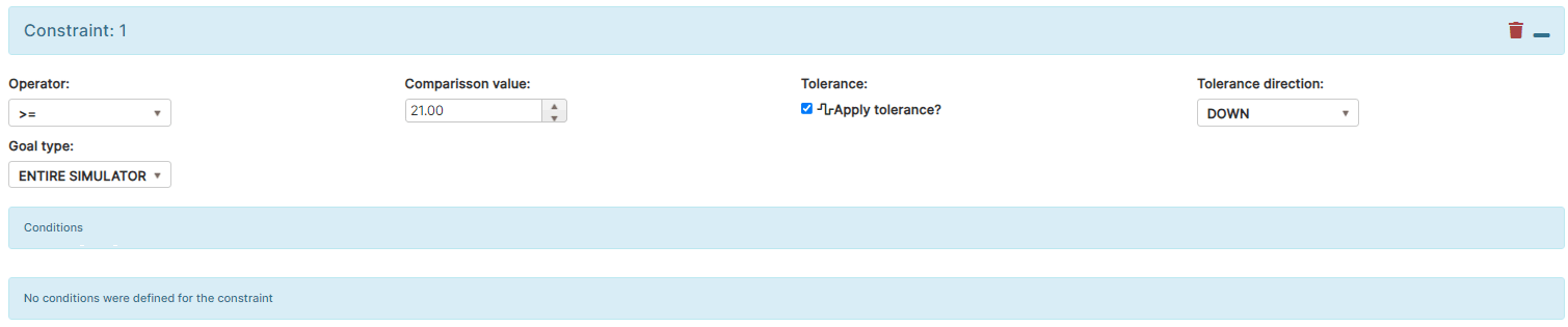
Figure 31: AI optimizer - Constraints – Constraint 1
Constraint 1 has a goal type entire simulator. Entire simulator means that all characteristics defined in the process simulator are subject to the constraint.
Constraint 1 applies to all characteristics from the process simulator when the value is greater than 21 degrees, including DOWN tolerance.
Constraint 1 has no conditions.
Constraint 2
Expand the constraint panel 2.
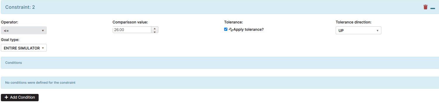
Figure 32: AI optimizer - Constraints - Constraint 2
Constraint 2 applies to all characteristics from the process simulator when the value is less than 26 degrees, including UP tolerance.
Constraint 2 has no conditions.
Constraint 3
Expand the constraint panel 3.
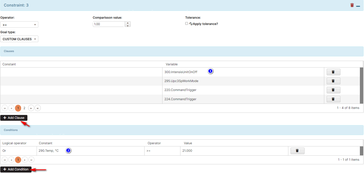
Figure 33: AI optimizer - Constraints - Constraint 3
Constraint 3 uses a Goal type Custom clauses.
To add a clause, click the Add Clause button.
In the clause it is possible to select as a constant, state characteristic or as a variable, control characteristic.
The clause may have one constant or one variable.
In the clause is added also conditions. Click the Add Condition button.
Condition has a logical operator, constant, operator, and value.
Constraint 3 means that when the temperature in zone 1 is higher than 21 degrees, at least one of the air conditioners must be turned on.
Click the Next button.
- Step 4 Objectives of AI optimizer opens.
Step 4: AI Optimizer Objectives
Objectives are displayed in the expandable panels.
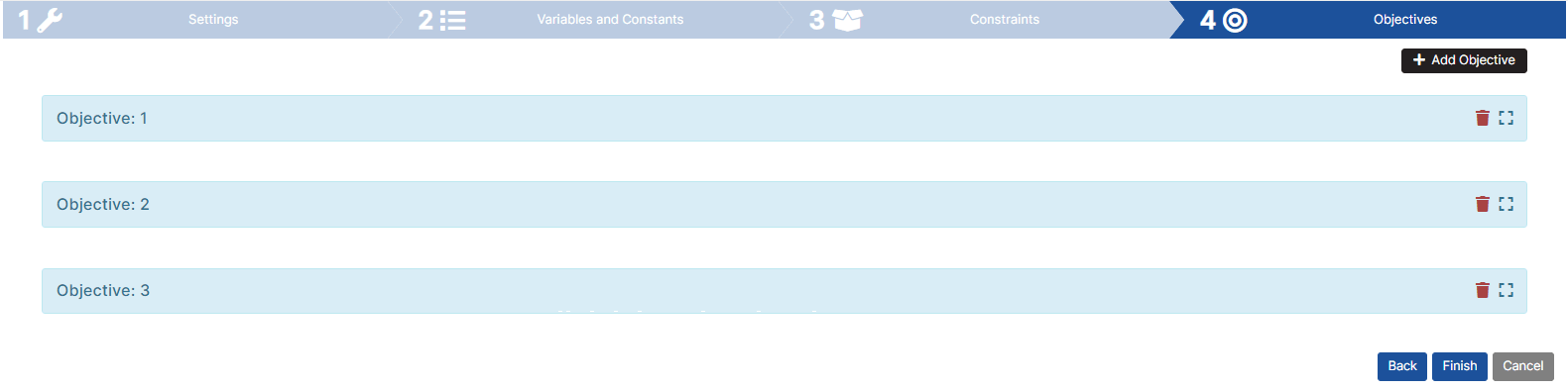
Figure 34: AI optimizer – Objectives
Click the Add Objective button.
- A new panel Objective is added to the page.
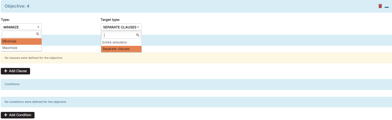
Figure 35: AI Optimizer - new objective
Each objective has a Type – Minimize or Maximize and Target types - Entire simulator or Separate clauses.
To remove the objective, click the remove button icon associated with the objective.
Each objective is an equation.
Objective 1
Expand the Objective panel 1.
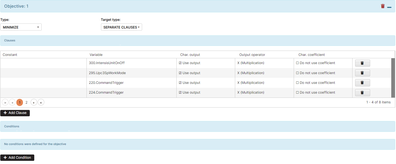
Figure 36: AI optimizer - Objectives - Objective 1
Objective 1 has type Minimize and target type Separate clauses.
To add clause, click the Add Clause button. Click on the cell Variable to select a control characteristic tag. From the organization tree, click on the machine and select a machine tag of type Int.
In Objective 1, the clauses are variables (control characteristics).
For each clause (variable) it is possible to choose:
- Char. output – select “Use output” or “Do not use output”.
- Output operator – select the operator when using characteristics output.
In Objective 1 it is checked to use Char. Output, and Output operator is multiplication. This means that in the equation we multiply characteristics by the output values.
The Output of the characteristics is calculated in Step 2: Process Simulator Output. In the output, we have calculated the energy used by air conditioners in kWh.
- Char. Coefficient – it is possible to select “Do not use coefficient” or “Use the coefficient” for the corresponding characteristic.
Coefficients of the characteristics are calculated in the Step 5: Process Simulator Preview & Train
If checked “Use coefficient” for clause this means the coefficients will be added to the equation.
For our example, the coefficients will not be used.
Objective 1 in the AI optimizer is to minimize the energy used by air conditioners.
Objective 2
Expand the Objective panel 2.

Figure 37: AI optimizer - Objectives - Objective 2
Objective 2 has a type Minimize, and a target type Entire simulator. Only conditions are stated in this objective.
The condition means:
- If we have a (tolerance>0) and
- (temperature in zone 1 is greater than 26 degrees and temperature in zone 2 is greater than 26 degrees)
- minimize the temperature in the whole simulator.
Objective 2 in the AI optimizer is to keep the temperature below 26 degrees.
Objective 3
Expand the Objective panel 3.
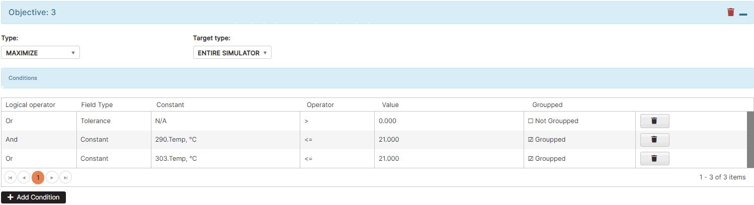
Figure 38: AI optimizer - Objectives - Objective 3
Objective 3 has a type Maximize, and a target type Entire simulator. Only conditions are stated in this objective.
The condition means:
- If we have a (tolerance>0) and
- (temperature in zone 1 is less than 21 degrees and temperature in zone 2 is less than 21 degrees)
- maximize the temperature in the whole simulator.
Objective 3 in the AI optimizer is to keep the temperature above 21 degrees.
AI Optimizer operation
The AI Optimizer works as an autonomous system.
- At each configured interval (e.g. 15 minutes) it is started.
- It calculates defined variables and constants, constraints, and objectives.
- For control characteristics (variables), it calculates values between the minimum and maximum values specified in the Step 1: AI Optimizer Variables and Constants and writes them to the control tags.
- For state characteristics (constants), it calculates values and writes them to the state tags.
- For each control characteristic, a device control command associated with the corresponding control tag is defined.
- If 0 is written in the control tag, a device control command turns off the air conditioner.
- If 1 is written in the control tag, a device control command turns on the air conditioner.
By turning on or off a group of air conditioners, AI optimizer achieves the goal of maintaining the temperature in the room within certain limits, with minimal energy consumption.