Calendars
Purpose: The Calendars menu is used to:
- Create shift templates with working hours and breaks for a week
- Set a machine shift template
- Remove the shift template from the machine
Select the menu Planning/Calendars.
- The page Calendars, tab Machine Calendar opens.
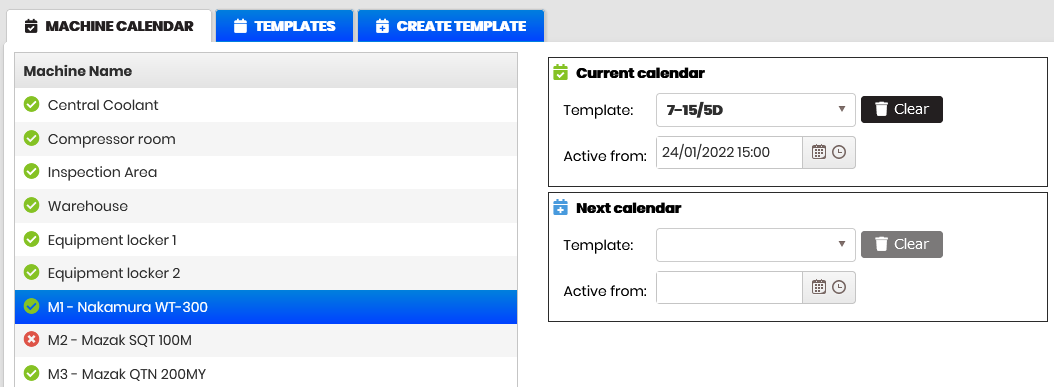
Figure 1: Planning - Calendars
Create a new shift template
Purpose: Create a new empty template for a shift.
To create a new template, select the tab Create template .
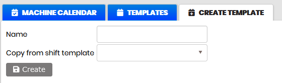
Figure 2: Calendars – create template
Enter the template name and click the Create button.
- An empty template is created with the entered name.
A new template can be created also by entering a name and selecting the existing template from the Copy from shift template list.
- A template is created with entered name equal to the selected template from the list.
The new template created is visible in the list of the Templates tab.
Fill in the template with shift hours
Purpose: The Templates page is used to:
- Browse the list of templates.
- View and plan shift templates with working hours and breaks.
- The shift template is scheduled for the selected time zone.
- Delete the selected template.
- Update hours/breaks for the selected template.
Click the tab Templates.
- The list of created shift templates is displayed there.
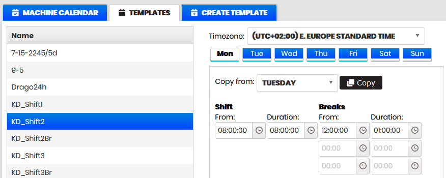
Figure 3: Calendars – planning the template schedule
Select shift template from the list
- A form is shown on the right for entering working hours (From, Duration), breaks (From, Duration), and Timezone. Monday is selected by default.
Enter for Monday in the shift From hours and Duration fields, hours selected from the drop-down list or entered manually in the fields.
Enter breaks (if necessary) in the Breaks fields in a similar manner.
- The shift graphic for Monday is ready.
For the other days of the week, it is possible to copy hours from an already configured Monday.
Click the Save button.
- Created shift template with hours and time zone is saved.
The created template can be deleted from the list. Select the template from the list and click the Delete button.
- The selected template is removed from the list.
Scheduled hours in the template can be changed multiple times and saved accordingly by pressing the Save button.
Assign a shift template to the machine
Purpose: Assign a machine shift template.
Click on the Machine calendar tab.
- The machine list is displayed.
- An icon is displayed in front of the machine number:
- Red icon - if no schedule is attached.
- Green icon - if there is a schedule attached.
Select a machine without shift template attached (it has a red icon).
- Current calendar and Next calendar forms appear on the right.
Open the templates drop-down menu in Current calendar and select a shift template.
In the Active from field, select a date and time from which the schedule will be active.
In the same way, fill in the Next calendar fields.
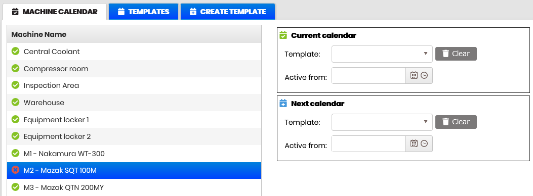
Figure 4: Calendars - machine calendars
- The icon in front of the machine number and name turns green, which means that the schedule is already attached.
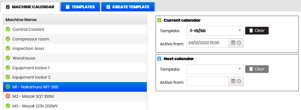
Figure 5: Calendars- machine with assigned shift template
Remove shift template from the machine
Purpose: Remove the shift template from the machine. Then again it is possible to set a new shift template.
Click on the Machine calendar tab. Select a machine from the list with a green icon. The Current calendar field shows the name of the shift template and the date and time from which the schedule is active.
Click the Clear button and confirm.
- The fields in the Current calendar form are cleared and icon in front of the machine number and name turns red.
For machines without shift template attached is possible to assign new shift template.
Operations
Purpose: Review and filter the ERP imported operations that will be scheduled as production orders. The section can be collapsed to increase the area of the plan with production orders per machine.
Preconditions: ERP planned operations for orders are automatically imported into the Upkip platform.
Select the menu Planning/Production orders.
- The page for viewing and filtering the operations imported from the ERP opens. Visually selected operations can be scheduled by dates and machines.
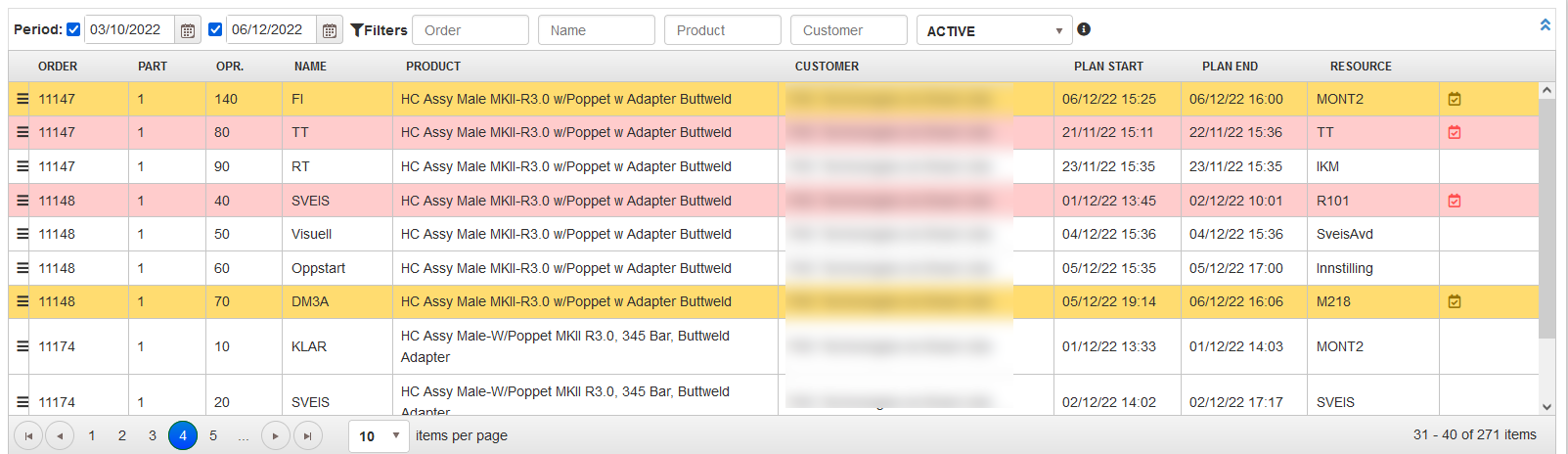
Figure 6: Planning – operations from ERP
View operations
Precondition: Select the menu Planning/Production orders.
The operations table is shown at the top of the page. Each operation is displayed on one row with data in the columns: order (number), part (number), operation (number), name (operation name), product (name), customer (name), date and time of the planned start and end of the operation, resource (name).
To show the status of the operation row is colored in different colors.
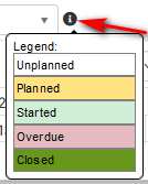
Figure 7: Planning - operation statuses legend
It is possible to expand or collapse the table with operations from the ERP clicking on the right side icon.

Figure 8: Planning - collapsed operations table
If you collapse the table operations table, the entire screen will be used for the Gantt with planned production orders by machine.
Filter operations
Multiple filters are used for filtering operations.
Filter by period
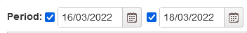
Figure 8: Operations – filter by period
With both dates highlighted and selected, all operations with a planned start greater than the first and planned end less than the second date are displayed.
With only the fist date checked, all operations with a planned start greater than the selected date are displayed.
With only the second date checked, all operations with a planned end less than the selected date are displayed.
Filter by order, name, product, and customer

Figure 9: Operations – filter by order, name, product, customer
Enter in the filter Order part of the order name.
- The table with operations is filtered automatically showing only the operations to orders containing in the order name entered text.
Enter in the filter Name part of the operation name.
- The table with operations is filtered automatically showing only operations with a name containing the entered text.
Enter in the filter Product part of the product name.
- The table with operations is filtered automatically showing only operations to products containing in the product name entered text.
Enter in the filter Customer part of the customer name.
- The table with operations is filtered automatically showing only operation to products for customers containing in the customer name entered text.
Filter by operation status
Operations can be filtered by the status selected from the dropdown filter. The predefined statuses are: Unplanned, Planned, Started, Overdue, Closed.
- The table with operations is filtered automatically.
Review details of the planned operation
Precondition: The operation has been planned by date and machine.
If operation has planned at the right column appears icon with tooltip Status and link Show details.
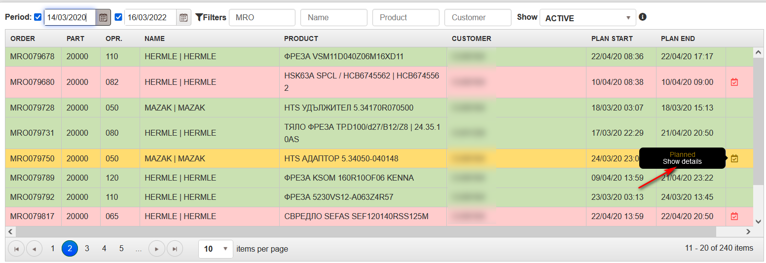
Figure 10: Operations – view details for planned operation
Clicking on the link Show details shows a popup with information
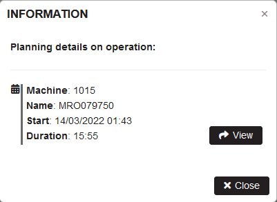
Figure 11: Operations- details for planned operation
In the form with information are shown: machine (number), name (order number), start (start date and time), and duration (hours and minutes).
Clicking on the View button, the production order is located in the plan and bordered with blue color.

Figure 12: Planned orders Gantt – the found order through view details
Production Orders
The functionalities are described in the section:
- Plan production orders
- Plan the orders in the machine schedule
- Plan the orders overtime
- View and edit production order
- Delete production order
- Assign operator to production order
Planning production orders
Purpose: Planning the operations imported from the ERP by dates and machines. The plan with production orders for one machine is displayed in line with orders, sequentially over time.
Select the menu Planning >Production orders
- There is opened page with operations and plan with production orders. The plan is on the bottom part of the page.
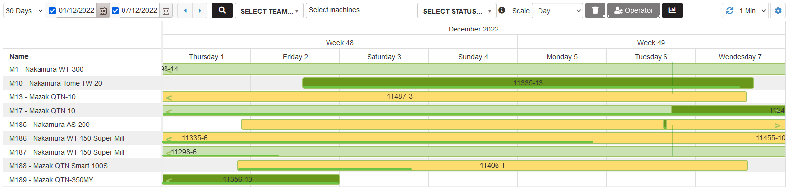
Figure 13: Plan with production orders by time and machines
Plan the orders in the machine schedule
Precondition: The machine is selected in the filter. The plan is filtered for the selected machine.
Click on the left icon from the row with an operation for planning in the operations table. Drag down to the plan and drop in the area with the title DROP HERE.
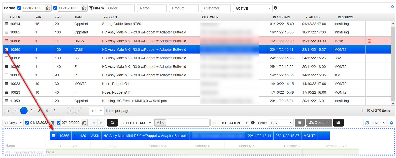
Figure 14: Planning production order
- There is opened the form Create production order:
- Automatically is loaded machine in the form
- Start date and time are loaded with the end date and time of the last planned order for the machine
- Duration shows the operation duration from the ERP with hours and minutes.
- The order Number shows – number of the order-number of the product-number of the operation
- Name of the order – number of the order from the ERP.
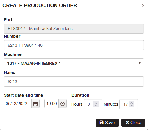
Figure 15: Planning – create production order
Click the Save button.
- If the duration of the operation goes outside the machine working time is shown warning with asking the choice how to continue

Figure 16: Planning - choice to plan in schedule or overtime on machine
Click the button Plan in schedule.
- The production order is planned only during the working hours of the machine, skipping the non-working hours and breaks. The color of the order reflects its status, according to legend. The non-working hours of the order are displayed with a lighter background.
- The name of the production order in the plan is the order number.

Figure 17: Planning – order planned in machine schedule
The row with the planned operation in the operations table is colored depending on the order status.
Plan the orders overtime
Precondition: The filter with machines is empty. After the last planned order for the machine there is a working time less than the duration of the next planned order.
Click on the operation from the operations table that is not planned. Drag down to the plan and drop in the area with the title DROP HERE.
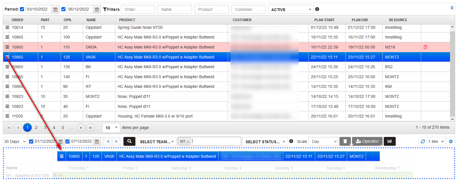
Figure 18: Planning – plan the order outside the machine schedule
- There is opened the form Create production order filled only with operation duration from the ERP. The duration of the order is longer than the working interval of the machine for the day.
Select a machine from the dropdown list for which to plan the order.
- Automatically are loaded Start date and time equal to the end date and time of the last planned order on the machine.
Click the Save button.
There is opened warning for the choice to plan in schedule or overtime.
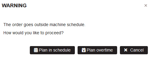
Figure 19: Planning – choice to plan in schedule or overtime
Click the button Plan overtime.
- The whole order will be placed after the last planned order and is also located during the non-working hours of the machine.

Figure 20: Planning – planning the order overtime
View and edit production order
The planned order in the plan with production order is possible to view or update by double click on the order in the plan or single click and click the button Update.
- There is opened the form Edit production order
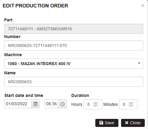
Figure 21: Planning – edit production order
There is possible to change the machine, the order name, start date and time, and duration of the order in hours and minutes. After clicking the Save button, the changes affect the order plan.
Delete production order
Precondition: There are the planned production orders for the period and machines.
From the plan with production orders are possible to delete only orders with the status Planned or Overdue (but not started).
Click on the order from the plan. The button Delete becomes active. Click on the button Delete.
- The order is removed from the plan with production orders.
- The corresponding operation in the operations table becomes unplanned (white background)
Assign operator to production order
Precondition: There are the planned production orders for the period and machines.
There is possible to assign operators only to production orders with Planned or Overdue (but not started).
Click on the order from the plan. The button Choose operator becomes active. Click the button Choose operator.
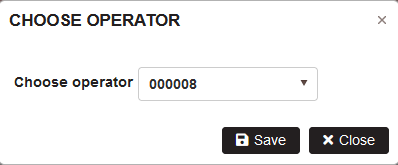
Figure 22: Planed production orders – assign operator
In the Choose operator form select the operator number from the dropdown list. Click the button Save.
- The operator is assigned to the selected production order
If click on the order with status Started or Closed, the buttons are disabled.
Plan settings
At the top right of the Gantt plan are located settings icon (1) and refresh options (2).
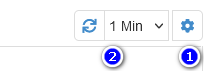
Figure 23: Refresh and settings
Click on the settings icon.
- The settings form is opened.
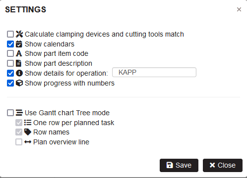
Figure 24: Gantt plan settings
Set automatic refresh interval
By default the Gantt plan with production order is refreshed each one minute. But the interval is possible to change by selecting 2, 5, or 7 min. Selecting Off is switched off the refresh of the Gantt plan.
Show calendars
Checking the settings option Show calendars in the Gantt plan are visualized on the machine row with grey color the machine nonworking time. With white color is the machine working time.
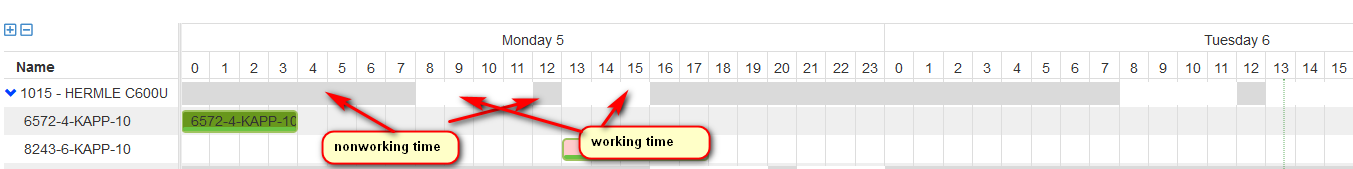
Figure 25: Gantt plan - settings - show calendars
Show part item code and part description
Checking the settings option Show part item code shows in the tooltip for production order the part item code.
Checking the settings option Show part item description shows in the tooltip for production order the part item description.
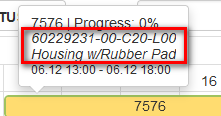
Figure 26: Gantt plan – View part item code and description
Show details for operation
There are two options for showing details for operation for the same part.
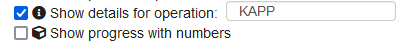
Figure 27: Settings - show details for operation
When checking Show details for operation and write in the field operation name, when pointing production orders on the tooltip is shown progress for operation for the same part number.
If only the first option is checked in the tooltip for production order are shown only percentages.
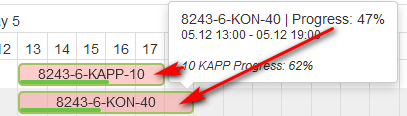
Figure 28: Gantt plan - tooltip for production order with operation details
If check the second option Show details with numbers for production order the specified operation are shown (good+scrip)/total planned.
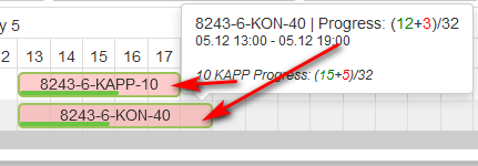
Figure 29: Gantt plan - tooltip for production order with numbers
Show the plan in a tree view mode
Purpose: Switch to tree mode for Gantt with production orders. Orders for machine are shown on separate lines each. There is possible to show title for each line with production order number. There is possible to show or hide the calendar assigned to the machine.
Open Settings form by clicking on the right side icon above the Gantt.
- The Settings form is opened.
Check the option Use Gantt chart tree mode

Figure 30: Gantt plan – Settings – tree view options
- The options One row per planned task and Row names are checked automatically.
- The Gantt plan is shown in tree view mode for each machine and each production order is on one separate line.

Figure 31: Planning - Gantt with production orders tree mode
Checking the settings option Plan overview line shows for each machine overview line showing the duration of orders for the selected time period.
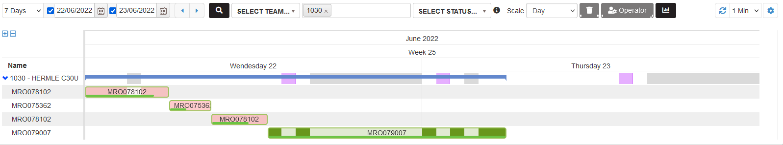
Figure 32: Planning - plan overview line for each machine
In the Gantt with production orders by light green vertical line is shown the current date and time.

Figure 33: Planning - vertical line for current date and time
Planning the production orders depending on match of cutting tools or clamping device
Purpose: When the last planned machine order is selected in the Gantt plan, in the operations table are displayed icons showing the match of cutting tools and clamping device or the number of changes of the cutting tools and/or clamping devices.
The aim is to plan sequentially as production orders operations with a minimum number of changes, to optimize the time for changing cutting tools and clamping devices.
Precondition: There are the planned production orders for the period and machines.
Select the menu Planning > Production orders.
- There is opened page with operations and plan with production orders. The plan is on the bottom part of the page.
In order to perform calculations for matches of cutting tools and clamping devices and display icons, it is necessary to select an option (checkbox) to enable the calculation of matches in the Settings.
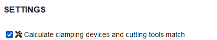
Figure 34: Settings – Calculate the matches for cutting tools and clamping devices
When this option is selected and the production order is clicked (selected), matching icons are displayed in the last column of the list with operations.
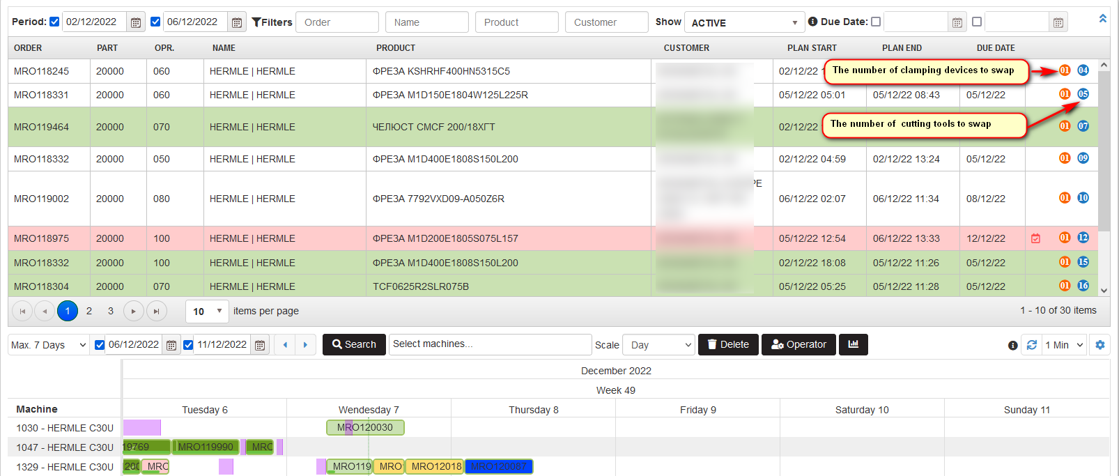
Figure 35: Planning – calculation of matches of cutting tools and clamping devices
With the icons for matching of cutting tools and clamping devices shown, the planner can choose from them and plan further production orders, minimizing the time to change the cutting tools and clamping devices.
If changes of cutting tools are necessary, a blue icon with a number indicates the number of changes of the cutting tools required for the respective operation.
If changes of clamping devices are necessary**, an orange icon with a number** indicates the number of changes of the clamping devices required for the respective operation.
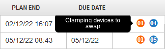
Figure 36: Planning – the number of clamping devices to swap
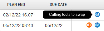
Figure 37: Planning – the number of cutting tools to swap
Filtering the plan with production orders
Filtering by machines
Precondition: There are the planned production orders for the period and machines.
Filtering the plan with production orders is possible by machines. It is possible to select more than one machine in the filter.
- In the plan are shown only lines with production orders for the selected machines
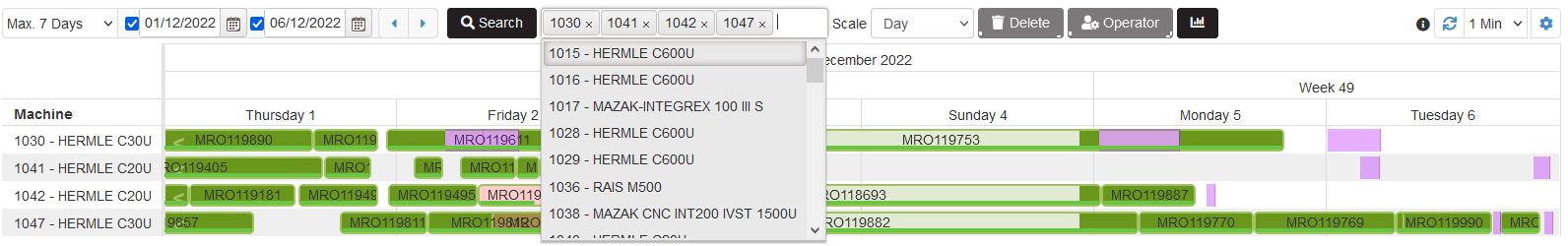
Figure 38: Plan with production orders – filtering by machines
Filtering by period
Filtering the plan with production order is possible by period. There is possible to filter only by start date, only by the end date or by both dates.
When checked and selected only first date or only second date, in the plan are shown 7 days after the start date or before the end date.
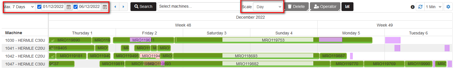
Figure 39: Gantt plan – filtering by period
When trying to select a period greater than 7 days is shown warning with a recommendation to select a smaller period. There are possible to select different max day range to show in a plan - 30, 45, 60, 90, or 180 days.
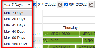
Figure 40: Gantt plan – max days range for period
There is possible to change the scale of the plan by selecting hour, day, or week. As a result, the plan is displayed at the selected scale.
Move to the next or previous planned period
Purpose: To select small (up to 7 days) or large (up to 30 days) to show the Gantt planning. Easily to review the plan by moving to the previous or to the next days defined by the filter.

Figure 41: Planning - change max days or move to the next/previous period
First is necessary to select the period range from the drop down predefined ranges - maximum to 7, 30, 45, 60, 90, or 180 days.
Then select period for the Gant plan by From-To dates.
Using the arrows is possible to review the previous or the next days defined by the From-To dates in the plan Gantt.
Filtering by team
Purpose: To filter the Gantt plan by a team.
When selecting a team from the predefined list on the Gantt plan are shown only machines with planned production orders belonging to the team.

Figure 42: Gantt plan - filtering by a team
Filtering by production orders status
Purpose: To filter the Gantt plan by production order status.
When selecting from a status dropdown filter some status in the Gantt plan are shown only orders with selected status for the selected time period.
Filtering is possible by: Active, Planned, Started, Overdue, Closed.
When selecting an Active in the Gantt plan are shown only production orders that are not closed.

Figure 43: Gantt plan - filtering by production order status
Plan with production orders – automatic positioning of the orders
Precondition: For one machine, production orders are sequentially planned over time.
Purpose: To maintain the plan with production orders for the machine one after the other. In case of changes in the duration of the planned order, those after it are automatically rearranged.
In case of changes in the orders in ERP as re-planning, the changes are reflected in the plan as order duration changes and the next orders will be automatically rearranged.
When checking downtime for the machine in the ERP and shifting the current order with the duration of downtime the next orders are automatically rearranged. Only started or closed orders are not moved.
Automatic positioning of the orders for machine is possible after the following actions:
- Manual changes of the order
- Re-planning the operation in the ERP
- Logs for produced details in the ERP
- Logs for downtime in the ERP
Automatic positioning of the orders after manual changes to orders
Precondition: For one machine, production orders are sequentially planned over time.
Purpose: In case of manual changes in one planned order, such as duration, the next orders after it with the status Planned or Overdue (but not started) are automatically rearranged one after the other.
We open the first order with a double click. The Change Production Order form is displayed. Increase the duration of the order and click Save and then Plan in schedule.
- The duration of the first order is increased
- The orders after it with the status Planned or Overdue (but not started) are automatically moved and rearranged in the plan.
- The orders with the status Started or Completed do not change in the plan
Automatic positioning of the orders after re-planning the operations in the ERP
Precondition: For one machine, production orders are sequentially planned over time.
Purpose: After re-planning the operation in the ERP, in the plan the duration of the corresponding production order is updated according to duration in the ERP. After it, all planned or overdue (but not started) orders are automatically rearranged in sequence.
After rescheduling the operation in the ERP, the planned times are synchronized in Upkip.
If the operation is planned for a machine as a production order, it is updated in the plan with the new duration from the ERP.
The planned or overdue (but not started) orders after the changed one are automatically rearranged in the plan with production orders.
The Started or Completed orders are not changed in the plan.
Automatic positioning of the orders after logs for produced details in the ERP
Precondition: For one machine, production orders are sequentially planned over time.
Purpose: In the production order plan, when an order has been completed, to show the actual duration of the order. After that, all planned or overdue (but not started) orders are automatically rearranged in sequence.
The actual start of a production order is determined from the time of the first log of manufactured parts in the EPR.
The end time of a production order is determined by the end time of the actual log for manufactured parts in the ERP when progress is 100%.
The completed order in the plan is presented with the actual duration of the work.
After that, all planned or overdue (but not started) orders are automatically rearranged in the production order plan.
The Started or Completed orders are not changed in the plan.
Automatic positioning of the orders after logs for downtime in the ERP
Precondition: For one machine, production orders are sequentially planned over time.
Purpose: In the production order plan to show the periods of downtime of the machine, which are determined by the checked start and end in the ERP. The duration of the order should be shown in the plan, excluding the periods of downtime.
When the end of a production order is moved due to downtime, the next planned or overdue (but not started) orders are automatically rearranged.
The actual start of a production order is determined from the moment of the first log of manufactured parts in the EPR.
During machine downtime, the ERP checks are made for the start and end of the downtime. The downtimes are automatically imported into Upkip with their reasons.
In the production order plan, the downtime is visualized with different color. On mouse over the drown downtime in the plan, the tooltip with downtime reason is displayed.
Planned Capacity
Precondition: There is created plan with production orders for machines.
Purpose: The planned capacity of machines per days show the percentage how much of the machine’s available hours are busy with production orders:
The planned capacity page shows:
- Capacity percentage of planned hours with production orders on machine vs available machine time per day.
- For each day and machine are shown as heat map percentages, planned, available hours, and the number of orders
- The planned capacity is for the selected period and list of machines. Machines could be filtered.
- Selected machines can be grouped and the chart will show the summary capacity percentage per day.
Select the menu Planning > Planned capacity.
- The Planned capacity page is opened.
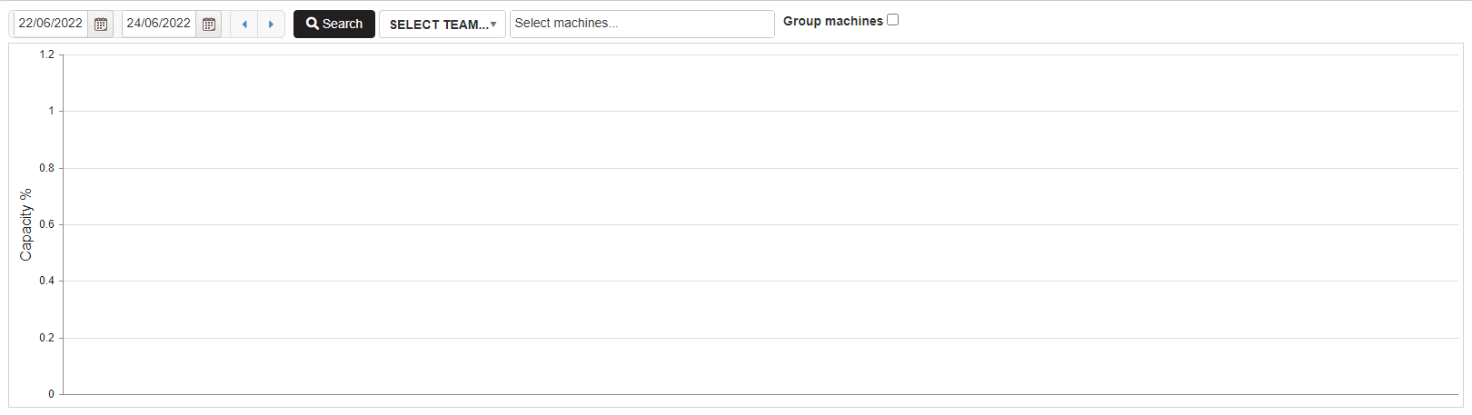
Figure 44: Planned capacity initial
Filters for showing the planned capacity.

Figure 45: Planned capacity filters
To show a chart with planned capacity per day select:
- Start and end of the period
- Optionally can be selected team and the machines in the next filter are filtered for the selected team
- Select machines from machines filter
- Click the Search button
- The chart with planned capacity of machines per day is shown.
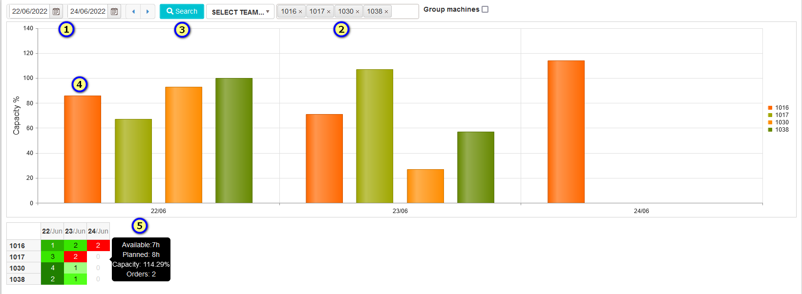
Figure 46: Planned capacity for the selected period and machines
The planned capacity of each machine is shown as a bar per day (4). The capacity percentage is shown on the mouse over the bar.
Under the graphics is shown a table as a heat map.
- Horizontally - dates from the selected period and vertically the list of selected machines.
- Each cell has a gradient color showing machine capacity per day. The colors are from light green (small capacity) to dark green (90%-100% capacity) or dark red (greater than 100%).
- With the mouse over the cells is shown tooltip with information (5) – available hours, planned hours, capacity, and number of orders.
Calculation of planned capacity for machine:
Machine planned hours per day are equal to the sum of production orders duration planned on the machine per day. (see Planning production orders)
Machine.PlannedHoursPerDay += OrdersDurationOnManiche[i]
Machine available hours per day are taken from the shift calendar assigned to the machine. (see Machine calendars)
Machine.AvailableHoursPerDay = MachineWorkinghoursDurationPerDay
MachinePlannedCapacity [%]= MachinePlannedHoursPerDay / MachineAvailableHoursPerDay
To show the summary capacity percentage of the selected machines check Group machines.
- For each day from the select period is shown one bar with a summary capacity percentage per day.
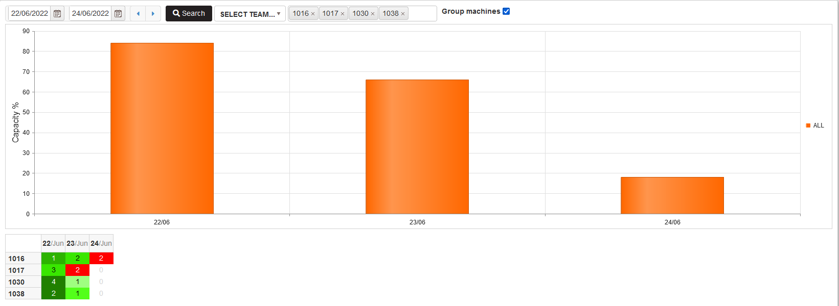
Figure 47: Planned capacity for group of machines per day
Calculation of Summary capacity percentage per day.
- AllPlannedHoursPerDay += Machine[i].PlannedHoursPerDay
- AllAvailablehoursPerDay += Machine[i].AvailableHoursPerDay
SummaryMachinesCapacityPerDay [%] = AllPlannedHoursPerDay / AllAvailablehoursPerDay
Move to the next or previous days with the period filter.
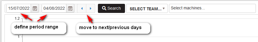
Figure 48: Capacity planning - move to next or previous period
After defining the period, selecting the machines and clicking the Search button is shown a chart and heat map table with the planned capacity for machines for the selected period.
Using the left and right arrows is possible to move to the next or previous period range. In this way, the user can easily review machines’ capacity planning for different periods.
Assistant
Create Asset
Precondition: Select the Assets menu. Select a department in the assets tree.
Click the menu Add/Asset.
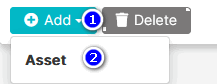
Figure 1: Select Add Asset menu
- The Add Asset form opens.
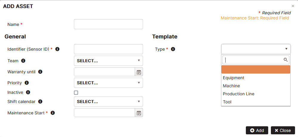
Figure 2: Add new asset
Fill in details for a new asset.
General properties:
- Name – the name of the asset.
- Identifier (Sensor ID) – unique identifier of the asset
- Team – select a configured team. Used to logically group or filter assets.
- Warranty until – select a date on which the warranty expires.
- Priority – select the machine maintenance priority from the configured list.
- Inactive – check if the asset is inactive.
- Shift calendar – it is possible to select a shift template for the asset from those configured in the company.
- Maintenance start – select a date when maintenance starts.
Template
- Type – select an asset type. Each type has different maintenance-related properties.
Click the Add button.
- The machine name appears under the department in the asset tree.
Assets in the Organization tree
Note!
An asset can be added to the organization tree using the Assets menu and Add Asset, populating the asset maintenance properties. Then, in the Organization menu, the asset is displayed if the “Show assets” option is checked.
The other way to configure an asset is when the machine is already configured via the Organization menu, then select the Assets menu and the machine in the asset tree and update the asset maintenance properties.
In the asset tree, if a machine has a gray icon, it means that the machine has no maintenance properties defined.
Click the created asset in the organization tree. Click the Tags tab. Filter by typing the MMS.
- The group of maintenance related tags are created automatically when the asset is created.
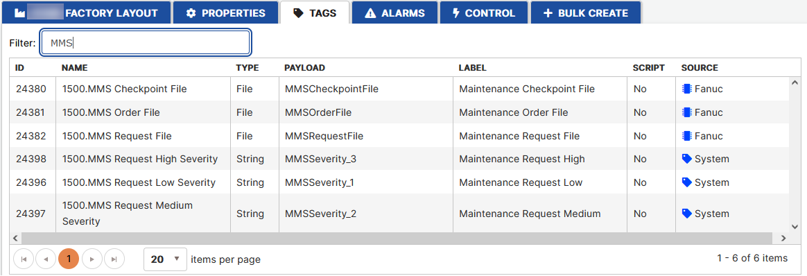
Figure 3: Asset maintenance related tags
Update Asset
Select the asset in the asset tree.
- The Properties, Counters and Checkpoints tabs are displayed on the right. Properties open by default.
Users can change the properties of the asset except the ID and type and click the Update button.
- The asset properties are updated.
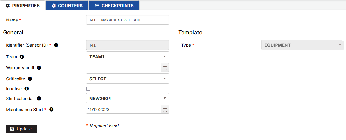
Figure 4: Update asset properties
Delete Asset
Precondition: Select the Asset menu. Select the asset in the asset tree.
Click the Delete button.
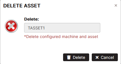
Figure 5: Delete asset
Click the Delete button again to confirm deletion.
- The asset is removed from the asset tree.
Assets List
Purpose: The asset list shows all assets in the selected department or factory.
Click the Assets menu.
- The list of company assets is displayed on the right.
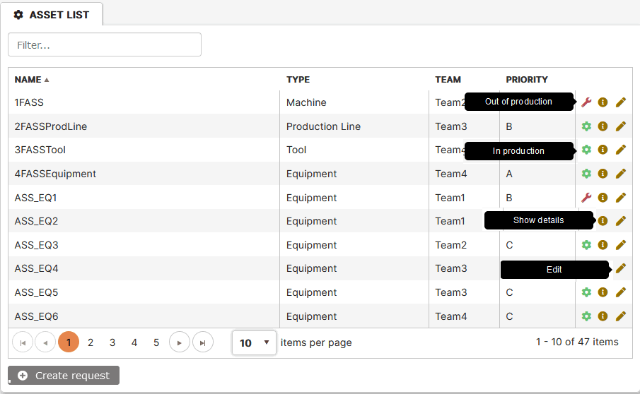
Figure 6: Asset list
The last column shows icons informing about:
- The asset state – “In production” or “Out of production”
- Clicking the edit icon or double-clicking the asset row opens the Asset Properties tab.
- Clicking the icon Show details opens the Status form.
Asset Status
Purpose: To show the 5 active orders and the last 5 of the completed orders.
The Asset status form displays two tables of active orders and completed asset maintenance orders.
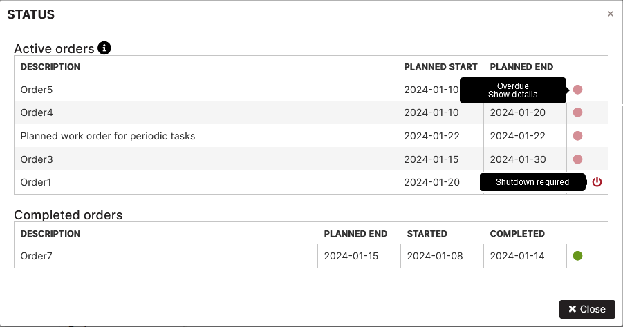
Figure 7: Asset status form
Table Active orders shows the 5 active maintenance orders with their description, planned start and planned end dates. The last column shows the statuses of the orders according to the legend and icon if the asset shut down is necessary.
Table Completed orders shows the last 5 completed maintenance orders with description, planned end, started, and completed dates**.** The last column shows the order status **Completed or Completed with delay.**
Hover your mouse over the info icon near the Active orders heading, the legend with order statuses is displayed.
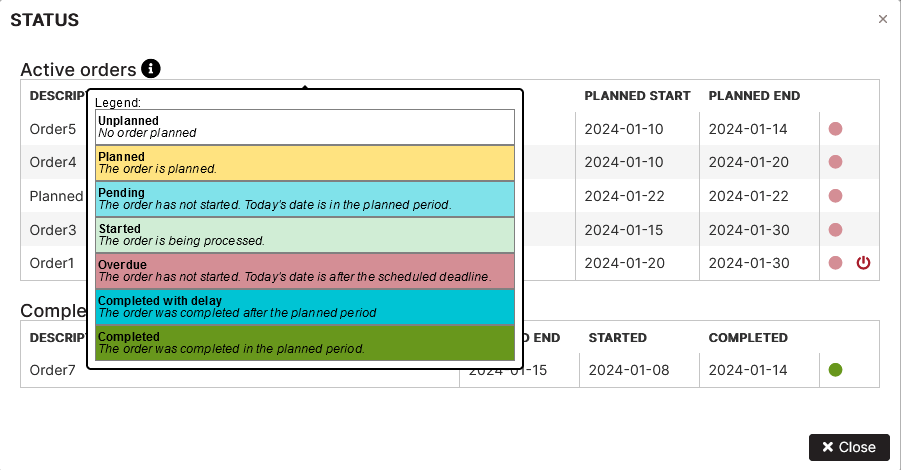
Figure 8: Legend with order statuses
Asset Counters
Purpose: To configure various types of counters on selected asset tag data.
Precondition: The asset tab Counters can be opened by:
- Select the asset in the asset organizational tree.
- Double-click the asset in the asset list.
Click the tab Counters.
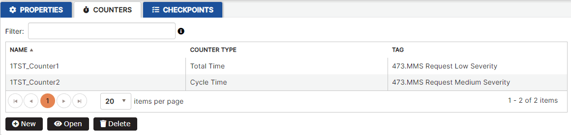
Figure 9: Asset counters list
To add a new asset counter, click the New button.
- The New counter form opens.
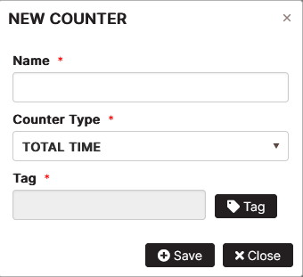
Figure 10: Add new counter for the asset
Fill in the Name, select a counter type from the list, select the tag from the list and click the Save button.
- The counter is created and appears in the list.
The counter list shows the counters created for the asset by name, counter type, and tag name.
To update the asset counter, click the counter in the list. Click the Update button.
The user can change the counter name and/or type and save it.
- The counter is updated.
To delete an asset counter, click the counter in list of asset counters. Click the Delete button. Confirm again with the Delete button.
- The asset counter is removed from the list.
Asset Checkpoints
Creating checkpoints for the asset means that these are scheduled machine maintenance tasks. Checkpoints have different types depending on the activity, outcome or how they are triggered.
Add Periodic Checkpoint
Periodic checkpoints are scheduled to inspect or replace parts of the asset during configured periods – daily, weekly, monthly, or yearly.
Precondition: Open the asset tab Checkpoints is possible by:
- Select the asset in the asset tree.
- Double-click the asset in the asset list.
Click the tab Checkpoints.
- The asset checkpoints list opens.
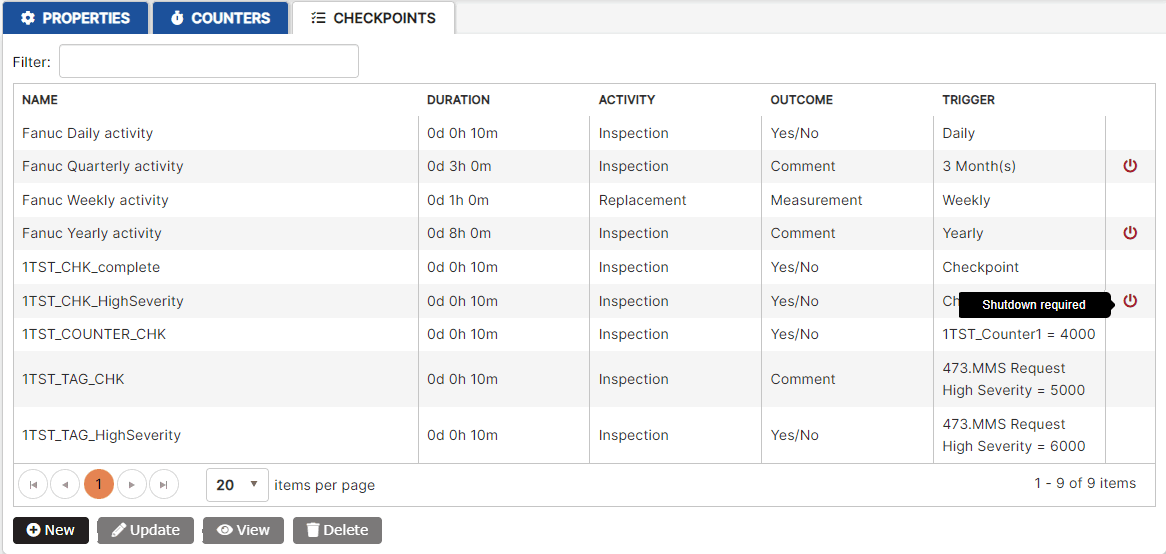
Figure 11: Asset checkpoints list
The checkpoints list displays the name, duration, activity, outcome, and trigger for each checkpoint. The last column shows an icon if asset shut down is required for the maintenance check.
To add a new asset checkpoint, click the New button.
- The Create maintenance checkpoint form opens. Advanced settings are collapsed.
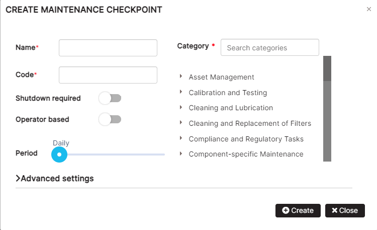
Figure 12: Create the asset maintenance checkpoint
Expand the Advanced settings to create a checkpoint.
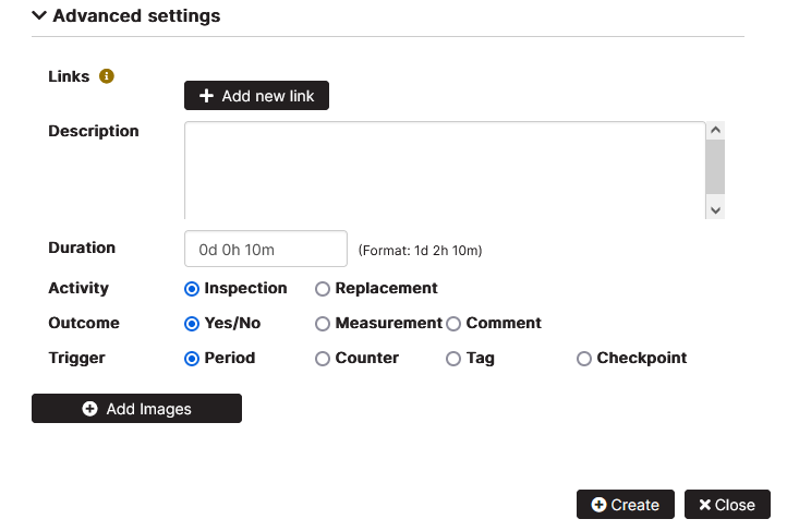
Figure 13: Asset checkpoint advanced settings
It is possible to create different checkpoints based on the selected activity, outcome, and trigger options selected.
Based on the Activity options selected, checkpoints can be performed as inspection or replacement of the asset parts.
Based on the Outcome options selected, checkpoints can be completed by selecting Yes or No, as a measurement performed or as a maintenance comment filled in.
Fill in the checkpoint’s name. The code is automatically filled in.
It is possible to turn on the option “Shutdown required” and “Operator based”.
Search by category and click a category from the list.
In the Description field, fill in details about the asset maintenance checkpoint. It is possible to add additional links to description documents.
In the Duration field, enter details about the duration of the maintenance checkpoint in days, hours, or minutes.
In the Trigger options the Period is selected by default.

Figure 14: Periodic checkpoint period
Users can select the period by moving the slider from Daily to Weekly, X Month(s), or Yearly.
It is possible to add photos related to the checkpoint by clicking the button Add images. The added image can be downloaded, viewed in a separate tab of the browser, or deleted. It is possible to add multiple images in the checkpoint.
Click the Create button.
- A periodic checkpoint appears in the list.
Add Counter-based Checkpoint
Counter-based checkpoints are triggered when the counter rule is met.
Precondition: The asset counter is defined. See Asset Counters list. The Asset Checkpoints tab is selected.
Click the New button. Fill in the required details for name and category. Fill in duration of the checkpoint. Select the activity, and outcome option.
In the trigger section, select the Counter option.
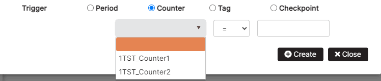
Figure 15: Create checkpoint with trigger counter
Select from the drop-down menu the counter defined for the asset, select a logical operator, and add a value. Click the Create button.
- A counter-based checkpoint appears in the list.
Add Tag-based Checkpoint
Tag-based checkpoints are triggered when the tag rule is met.
Precondition: The Asset Checkpoints tab is selected.
Click the New button. Fill in the required checkpoint details.
In the trigger section, select the Tag option.
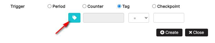
Figure 16: Create checkpoint with trigger tag
Click the icon to select a tag from the list of asset tags. Select a logical operator and add a value. Click the Create button.
- A tag-based checkpoint appears in the list.
Add Checkpoint-based Checkpoint
Checkpoint-based checkpoints are triggered when the selected checkpoint is completed.
Precondition: The Asset Checkpoints tab is selected.
Click the New button. Fill in the required checkpoint details.
In the trigger section, select the Checkpoint option.
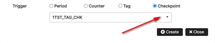
Figure 17: Create checkpoint with trigger another checkpoint completion
Select the checkpoint from the asset checkpoints drop-down list. Click the Create button.
- A checkpoint associated with the completion of the selected checkpoint appears in the list.
View Checkpoints
Purpose: Open the read-only view of the checkpoint settings.
Precondition: The asset is selected in the asset tree. The asset Checkpoints tab** is selected. The list of defined maintenance checkpoints of the asset is displayed.
Click the checkpoint from the list. The checkpoint is selected.
Click the View button.
- The Maintenance checkpoint form displays read-only checkpoint settings.
The form shows the checkpoint main settings such as name, category, shutdown required, operator base, description, duration, activity, outcome, and trigger.
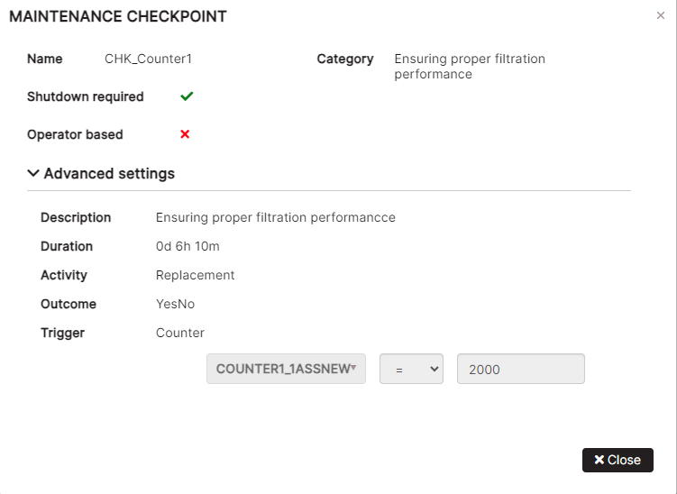
Figure 18: View maintenance checkpoint
Register Progress
Purpose: Review of the operator logs for produced good or scrap quantities for operation.
Precondition: On the page Assistant are shown production orders for the selected date.
For the selected order click on the icon in column Timetracking.
- The Register progress form is opened with loaded records for produced details (if any)
Data are shown in a table with columns: operator, machine, order (number), position (number), part (description), operation (number), start (date and time), end (date and time), good, scrap.
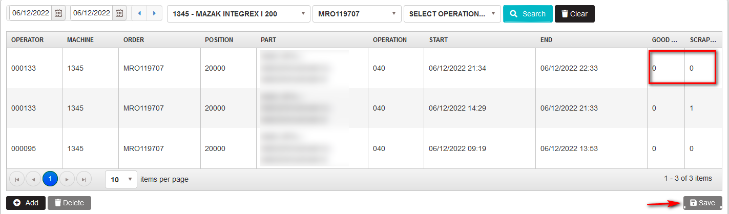
Figure 52: Register progress – reported time and units from the operator for the order
By clicking on the cells in the columns Good and Scrap for the respective order, user can make the adjustments of the numbers and save by clicking on the Save button.
- The numbers of the good and scrap are saved
The user with the role Shift Leader is possible to add records for produced units from the operators for the orders by clicking on the Add button.
- The form Add is opened
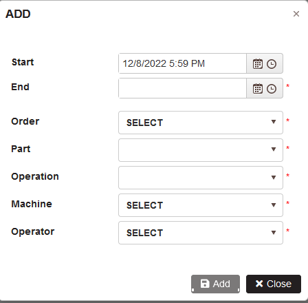
Figure 53: Add records for produced details from operator for order with start and end date and time
Select start and end date and time, operator, machine, order, operation and part.
Click Add.
- A row with operator log for produced details is added.
Enter the numbers for good the scrap details and click Save.
- The record with working date and time and produced details from the operator is added.
Select a row with working time and produced details from operation. Click Delete.
- The record is removed from the table.
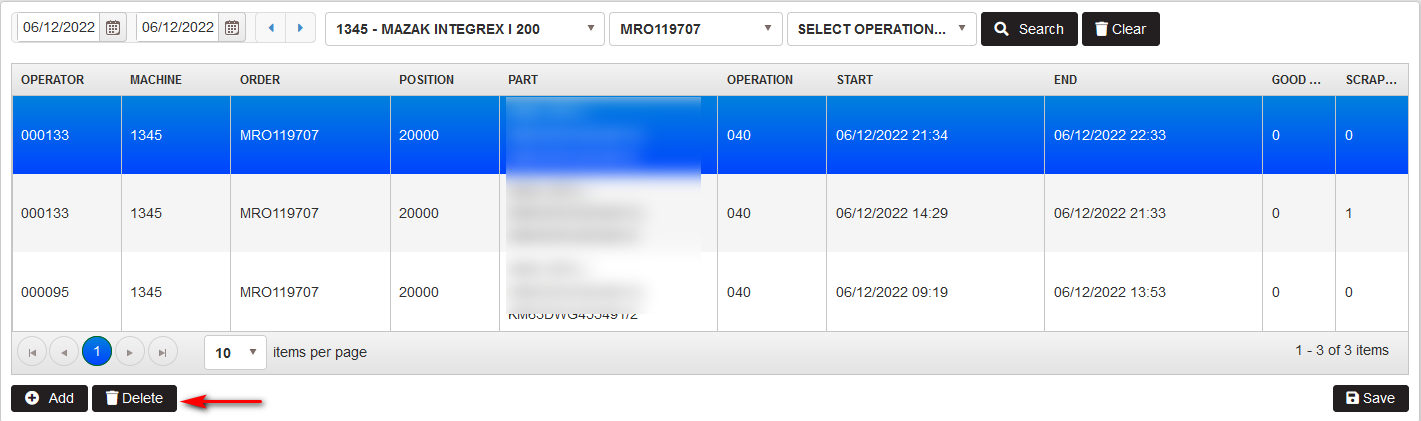
Figure 54: Register progress – deleting record