Overview
Purpose: The Tool Management module is used to:
- Configuration of types and instances of clamping devices, adaptive items, cutting items, and cutting tools used in production.
- See real-time locations of cutting tools and clamping devices.
- Change the locations of cutting tools and clamping devices.
- Configuration management of machine controllers and scan heads.
The section described:
Tool management is accessible from the main menu.
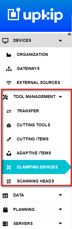
Figure 1: Upkip Main menu - Tool Management menu
Cutting Items
Purpose: The Cutting items menu is used to:
- View or create Cutting items types.
- Upload and download the drawings attached to cutting items types.
- See attached instances to each type.
- Create and Delete the Cutting items instances.
The Cutting items types with their drawings are imported from the ERP system or created manually.
The section describes:
Cutting Item Types
Select the menu Tool Management/ Cutting Items.
- The Cutting Items Types page opens.
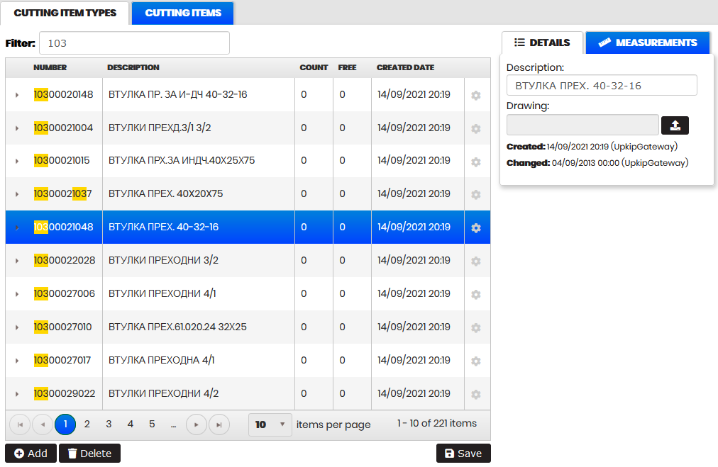
Figure 2: Cutting Items - Cutting item types
The table shows the cutting item types with number, description, count (number of instances of this type), free (number of free instances not used in the cutting tools), and created date.
It is possible to filter the cutting item types by entering part of the number or description of the type in the Filter field.
- The table is automatically filtered.
Selecting a row from the table opens Details on the right side with a description and attached drawing. It is possible to upload or download the type drawing.
Clicking the arrow to the left side of the row expands the type with the list of instances created with it. Each instance is displayed with number, status, and created date.
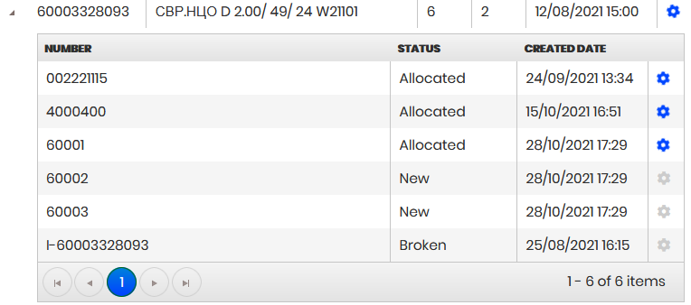
Figure 3: Cutting item type with attached instances
The table can be sorted by all columns clicking on the column headings.
Click on the Add button.
- The Create Cutting item type form opens.
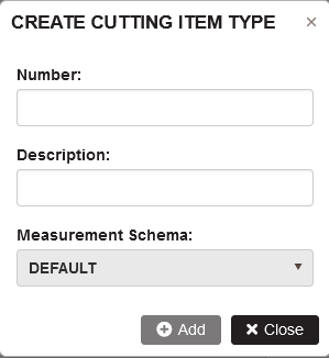
Figure 4: Cutting items - Add Cutting item type
Enter a number and description, select measurement scheme, and click Add.
- The new cutting item type is added and appears in the table.
Select any line of cutting item types that has no attached instances of cutting items. Click Delete.
- The cutting item type is deleted and removed from the table.
Select any line of cutting item types with Count greater than zero and click Delete. Confirm.
- A message is displayed that the type has attached cutting items and cannot be deleted.
Cutting Items
Precondition: Select the menu Cutting items. Click the tab Cutting items.
- The Cutting items page opens.
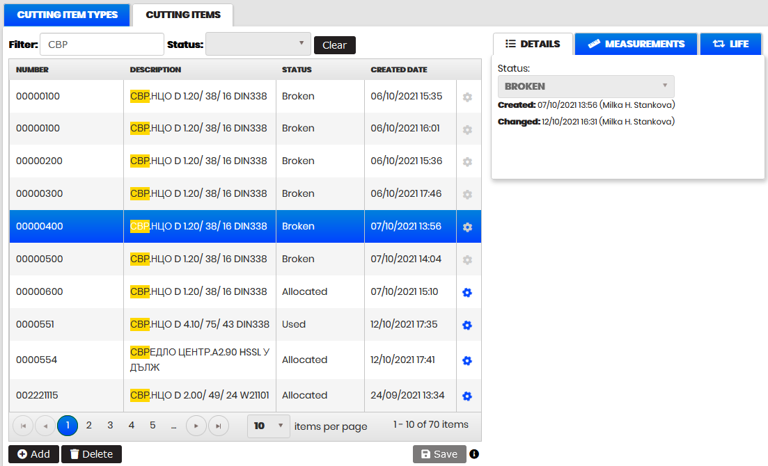
Figure 5: Cutting item - Details
The table shows cutting items with number, description of type, status, created date, and icon of use (blue and rotating icon - if used in a cutting tool or grey icon – when it is not used).
It is possible to filter the cutting items entering part of the number or type in the Filter field .
- The table is automatically filtered.
Filtering by status is possible from the Status filter.
Clicking the Clear button clears all filters and shows the table with all cutting items.
Selecting a row from the table opens Details on the right side. It is possible to change the status of the cutting item from the Status drop-down menu.
Click the tab Measurement on the right side. All parameters that are measured by the Presetter Zoller machine are listed there. After measuring the cutting items, the data is automatically filled in and saved in the cutting tool.
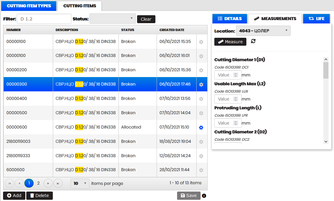
Figure 6: Cutting item - Measurements
The table can be sorted by all columns clicking on the column headings.
Click on the Add button.
- Create Cutting item form opens.
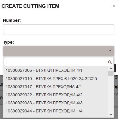
Figure 7: Create Cutting item - select Cutting item type
Filter the Cutting item types by typing in the search field. Select a type from the drop-down list.
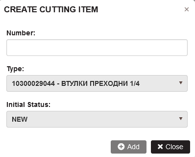
Figure 8: Create Cutting item - all controls
Enter the cutting item number and select the initial status from the drop-down list.
Click the Add button.
- The new cutting item is created and appears in the table.
Select any line of cutting items that is used in a cutting tool, and click Delete. Confirm.
- A message is displayed that cannot delete the cutting item because it is used by a tool with RFID
.
Select any line with the cutting items that is not used in a cutting tool and click Delete. Confirm.
- The cutting item is deleted and removed from the table.
Adaptive Items
Purpose: The Adaptive items menu is used to:
- View or create adaptive items types and instances.
- Upload and download the drawings attached to adaptive items types.
- View attached instances to each type.
- Add or delete adaptive items.
The adaptive items types with their drawings are imported from the ERP system or created manually.
The section describes:
Adaptive Item Types
Select the menu Tool Management/Adaptive Items.
- The Adaptive Items Types page opens.
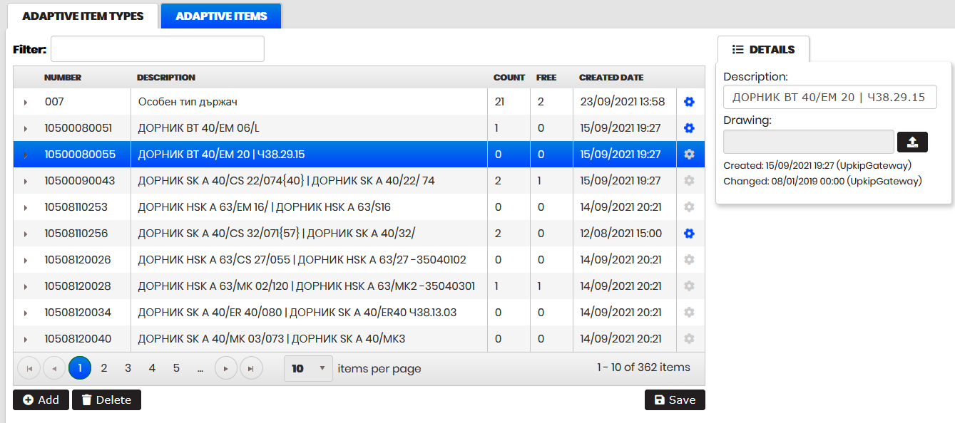
Figure 9: Adaptive Items - Adaptive item types
The table shows adaptive item types with number, description, count (number of instances of this type), free (number of free instances not used in the cutting tools), and created date.
It is possible to filter the adaptive item types by entering part of the number or description of the type in the Filter field.
- The table is automatically filtered.
Selecting a row from the table opens Details on the right side with description and attached drawing. It is possible to upload or download the type drawing.
Clicking the arrow to the left side of the row expands the type with the list of instances created with it. Each instance is shown with RFID and created date.
The table can be sorted by all columns clicking on the columns headings.
Click on the Add button.
- Create Adaptive item type form opens.
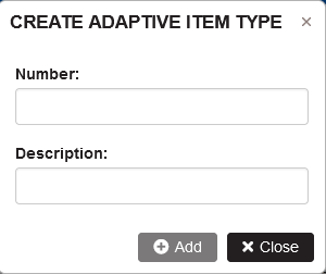
Figure 10: Adaptive items - Add adaptive item type
Enter a number and description and click Add.
- The new adaptive item type is added and appears in the table.
Select any line of adaptive item type that has no attached instances of adaptive items. Click Delete.
- The Adaptive item type is deleted and removed from the table.
Select any line of adaptive item type with Count greater than zero and click Delete. Confirm.
- A message is displayed that the type has attached adaptive items and cannot be deleted.
Adaptive Items
Precondition: Select the menu Adaptive items.
Click the tab Adaptive items.
- The Adaptive items page opens.
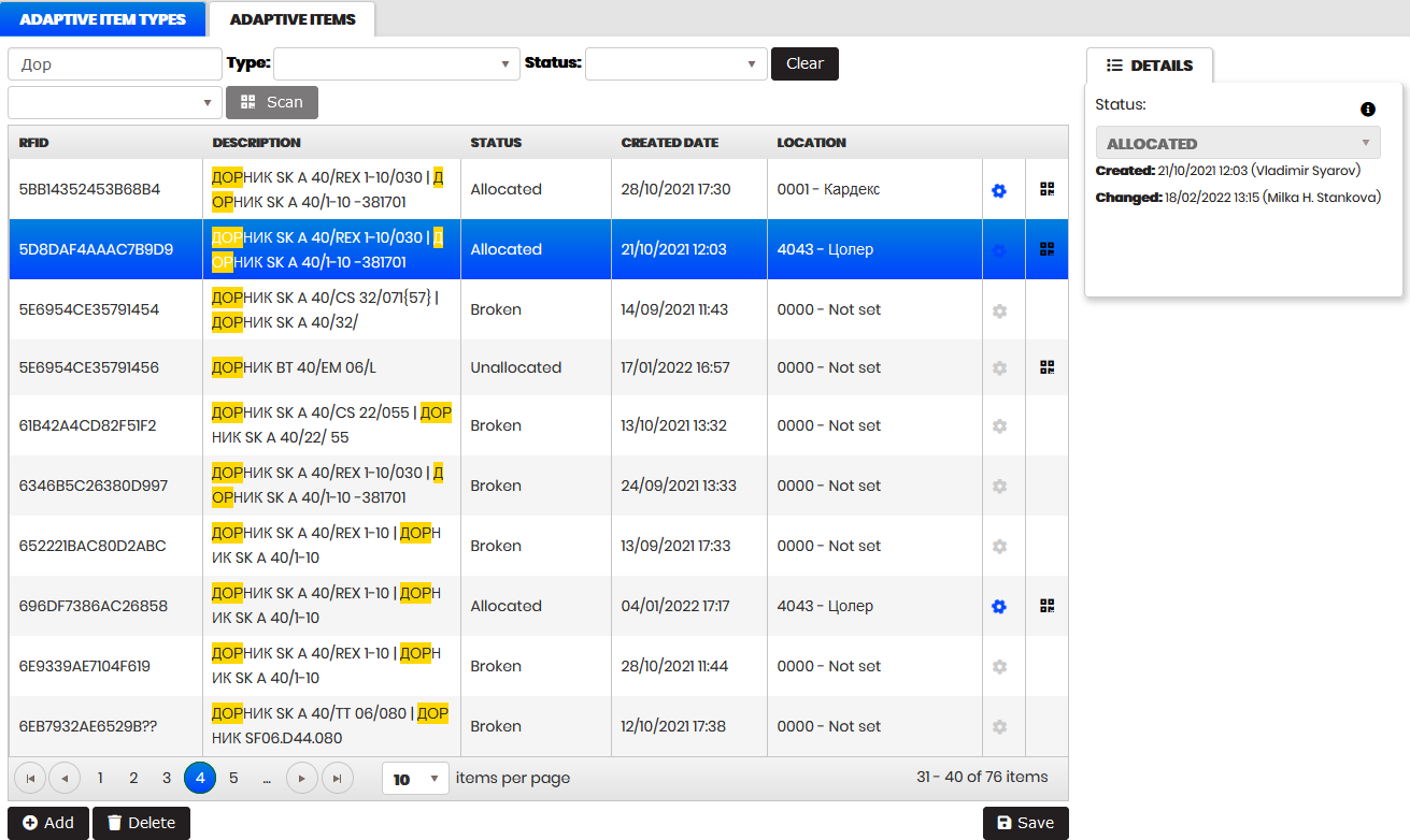
Figure 11: Adaptive items
The table shows the adaptive items with RFID, type, status, created date, location, icon for use (blue and rotating icon - if used in a cutting tool or grey icon – when is not used), and icon for changing RFID.
It is possible to filter the adaptive items by entering part of the RFID or type in the Filter field.
- The table is automatically filtered.
Filtering by status is possible from the Status filter. Filtering by type is possible by the Type filter.
To scan the adaptive item RFID:
- Select the location from the drop-down list.
- Click the Scan button and then scan the RFID.
- Via push notification, the scanned RFID is sent to the Filter field and the table is filtered. The scanned adaptive item is attached to the selected location.
Clicking the Clear button clears all filters and displays the table with all adaptive items.
Selecting a row from the table opens Details on the right side. It is possible to change the adaptive item status from the Status drop-down list.
The table can be sorted by all columns clicking on the column headings.
Click on the Add button.
- Create Adaptive item form opens.
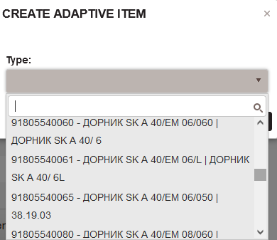
Figure 12: Create adaptive item - select adaptive item type
Filter the adaptive item types by typing in the search field. Select a type from the drop-down list.
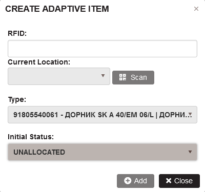
Figure 13: Create adaptive item - all controls
Select a location and click the Scan button.
Scan the RFID of the adaptive item.
- RFID is sent via push notification and filled in the RFID field.
Click the Add button.
- The new adaptive item is created and appears in the table.
Select any line of adaptive item that is used in a cutting tool, and click Delete. Confirm.
- A message is displayed “Cannot delete adaptive item. It is in use by tool with RFID:RFID”
Select any line of adaptive item that is not used in a cutting tool and click Delete. Confirm.
- The adaptive item is deleted and removed from the table.
Change adaptive item RFID
Select an adaptive item by clicking on the row. Click the icon Change RFID from the last column.
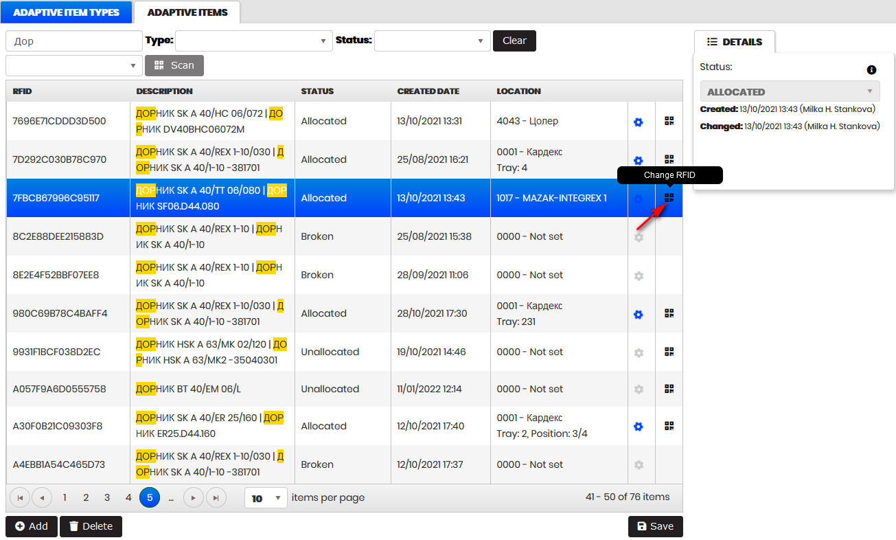
Figure 14: Adaptive items - open the form Change RFID
- The Change RFID form opens.
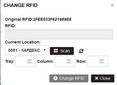
Figure 15: Change RFID of an adaptive item
On first scan, select a current location from the list and click the Scan button. Scan the adaptive item.
- The scanned RFID is loaded into the RFID field.
- With a Cardex location selected, it is possible to change RFID without entering tray, column and row.
Click the Change RFID button.
- The adaptive item gets the new RFID.
Selecting a new adaptive item and clicking the Change RFID icon, automatically loads the current location with already used ones and selects the Scan button.
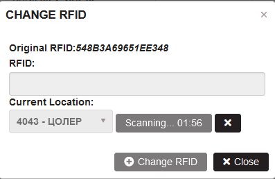
Figure 16: Scanning RFID with saved current location
User can scan an adaptive item and save by clicking the Change RFID button.
Cutting Tools
Purpose: The Cutting tools menu is used to:
- View or create the Cutting tools types.
- Upload and download the drawings attached to the cutting tool types.
- View attached instances of each type.
- Create or delete the instances of Cutting tools .
The Cutting tools types with their drawings are imported from the ERP system or created manually.
The section describes:
Cutting Tool Types
Select the menu Tool Management/Cutting tools.
- The Cutting Tool Types page opens.
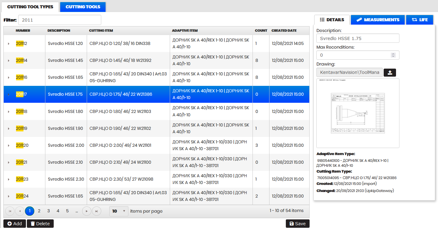
Figure 17: Cutting tools - Cutting tool types
The table shows cutting tool types with number, description, count (number of instances of this type), free (number of free instances not used in the cutting tools), and created date.
It is possible to filter the cutting tool types by entering part of the number or description of the tool the Filter field .
- The table is automatically filtered.
Selecting a row from the table opens Details on the right side with description and attached drawing. It is possible to upload or download the drawing of the type.
Clicking the arrow to the left of the row expands the type with the list of instances created with it. Each instance is displayed with RFID, status, and created date.
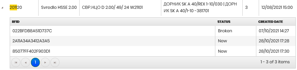
Figure 18: Cutting tool type with attached instances
The table can be sorted by all columns clicking on the column headings.
Click the Add button.
- Create Cutting tool type form opens.
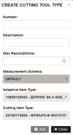
Figure 19: Cutting tools - Add Cutting tool type
Enter the number, description, max reconditions(optional), adaptive item type, and cutting item type. Click the Add button.
- A new cutting tool type is added and appears in the table.
Select any line of cutting tool type that has no attached instances of cutting tools to it. Click Delete.
- The cutting tool type is deleted and is removed from the table.
Select any line of cutting tool type with Count greater than zero and click Delete. Confirm.
- A message is displayed that the type has cutting tools attached and cannot be deleted.
Cutting Tools
Precondition: Select the menu Cutting tools. Click the Cutting tools tab.
- The Cutting tools page opens.
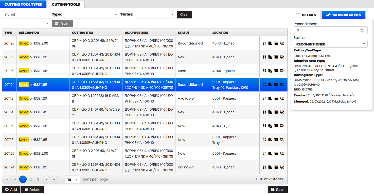
Figure 20: Cutting tools - Details
The Table shows cutting tools with type number, type description, cutting item type description, adaptive item type description, status, location and column with icons for cutting tool management.
It is possible to filter the cutting tools by entering the part of the RFID, cutting tool type, cutting item, cutting item type, adaptive item, or adaptive item type in the Filter field.
- The table is automatically filtered.
Filtering by status is possible from the Status filter. Filtering by type is possible from the Type filter .
To scan the RFID of the cutting tool:
- Select the location from the drop-down list.
- Click the Scan button, and then scan the RFID.
- Via push notification, the scanned RFID is sent to the Filter field and the table is filtered. The scanned cutting tool is attached to the selected location.
Clicking the Clear button clears all filters and shows the table with all cutting tools.
Selecting a row from the table opens Details on the right side. It is possible to change the cutting tool status from the Status drop-down and click Save.
Click the tab Measurement on the right side. There are listed all cutting tool parameters that are measured on the Presetter Zoller machine. After measuring the cutting tool parameters and the cutting item parameters are filled automatically and saved to the cutting tool.
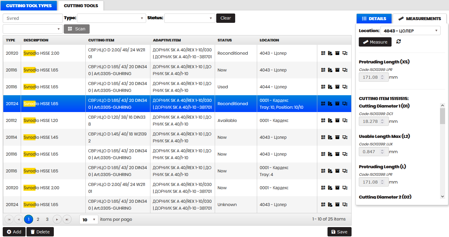
Figure 21: Cutting tool and cutting item - Measurements
The table can be sorted by all columns clicking on the column headings.
Click the Add button.
- Create Cutting tool form opens.
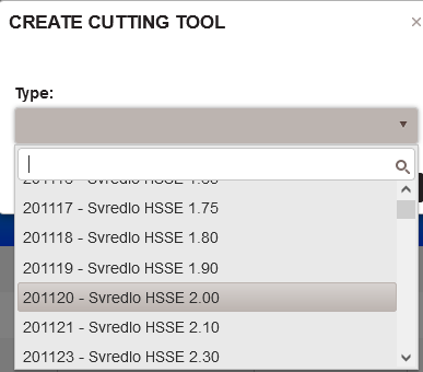
Figure 22: Create Cutting tool - select Cutting tool type
Filter the types of cutting tools by typing in the search field. Select a type of cutting tool.
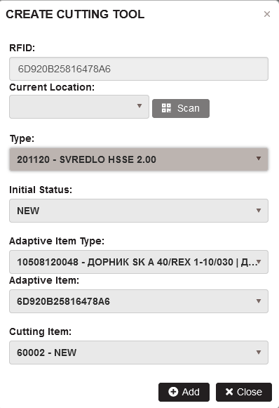
Figure 23: Create Cutting tool
Select a location and click the Scan button.
- Scan the RFID of the Cutting tool (this is an Adaptive item RFID).
- RFID is sent via push notification and fills the RFID field in the form.
- The adaptive item type is automatically populated with the adaptive item type of the scanned adaptive item.
- Select the Cutting item from the drop-down list (it is automatically populated with the cutting items of the required cutting item type).
- Select an initial status from the Initial Status drop-down list.
- If the adaptive item is scanned on Kardex, input of tray and position is required.
Click the Add button.
- The new cutting tool is created and appears in the table.
When you create a cutting tool and it lacks adaptive items of the required adaptive item type, it is possible to select another adaptive item type, or scan the available adaptive items.
- There is possible to create a cutting tool with a non-standard adaptive item.
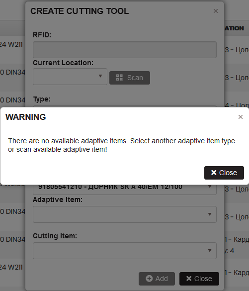
Figure 24: Create cutting tool with nonstandard adaptive item
Select any line of cutting tools and click the Delete button. Confirm.
- The cutting tool is deleted and removed from the table.
Cutting tools management
Precondition: The menu Cutting tools is selected. One cutting tool is selected in the table.
Purpose: The following operations are possible for the selected cutting tool:
Operations are accessible from the icons in the last column of the cutting tools table.
Change RFID
Purpose: It is possible to change the cutting tool RFID by scanning a new adaptive item RFID. The cutting tool can be saved with the scanned new RFID.
Select a cutting tool by clicking on the row. Click on the Change RFID icon from the last column.
Figure 25: Cutting tools - open the form Change RFID
- Change RFID form opens.
On first scan, select a current location from the list and click the Scan button. Scan the cutting tool (adaptive item).
- The scanned RFID is loaded into the RFID field.
Click Change RFID button.
- The cutting tool(adaptive item) receives the new RFID.
When you select a new cutting tool and click the Change RFID icon, the current location is now loaded and the button Scan is selected.
Figure 26: Scanning RFID with saved current location
User can scan a cutting tool (adaptive item) and save by clicking the Change RFID button.
Change cutting item
Purpose: If the cutting item in the cutting tool is broken or expired, it is possible to select a new cutting item of the desired type in the cutting tool. The old cutting item receives the selected status (Broken or Expired).
Precondition: A cutting tool row is selected from the cutting tools table. Click on the first icon from the last column.
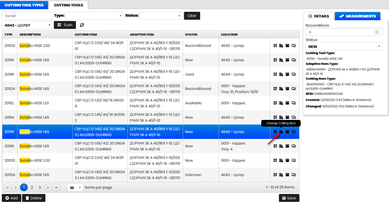
Figure 27: Cutting tools - Open Change cutting item form
- Change cutting item form opens.
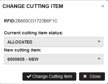
Figure 28: Change Cutting item of the cutting tool
The current cutting item status is automatically selected in the form . If a new cutting item of the desired type is available, it is selected in the New cutting item drop-down.
Select the cutting item status to Broken or Expired. Select a new cutting item (if exist) and click the Change Cutting Item button.
- Current cutting item gets selected status (Broken or Expired).
- The selected new cutting item is included in the cutting tool.
Return to storage
Purpose: The selected cutting tool can be returned to the Kardex storage with a selected status (Expired for example).
Precondition: A cutting tool is selected from the cutting tools table. Click on the second icon from the last column.
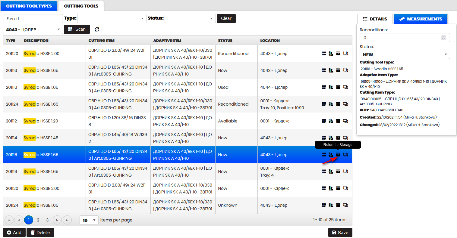
Figure 29: Cutting tools - Open Return to storage form
- Return to storage form opens.
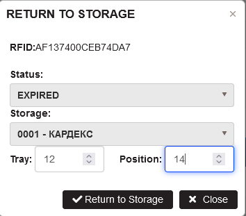
Figure 30: Return the cutting tool to storage
Select the status of a returned to storage cutting tool in the form.
Enter a Kardex tray and position. Click the Return to Storage button.
- The cutting tool with selected status is returned to the Kardex storage in the specified tray and position.
Disassemble cutting tool
Purpose: The selected cutting tool can be disassembled and the cutting item and the adaptive item can be given the selected statuses.
Precondition: A cutting tool is selected from the cutting tools table. Click on the third icon from the last column.
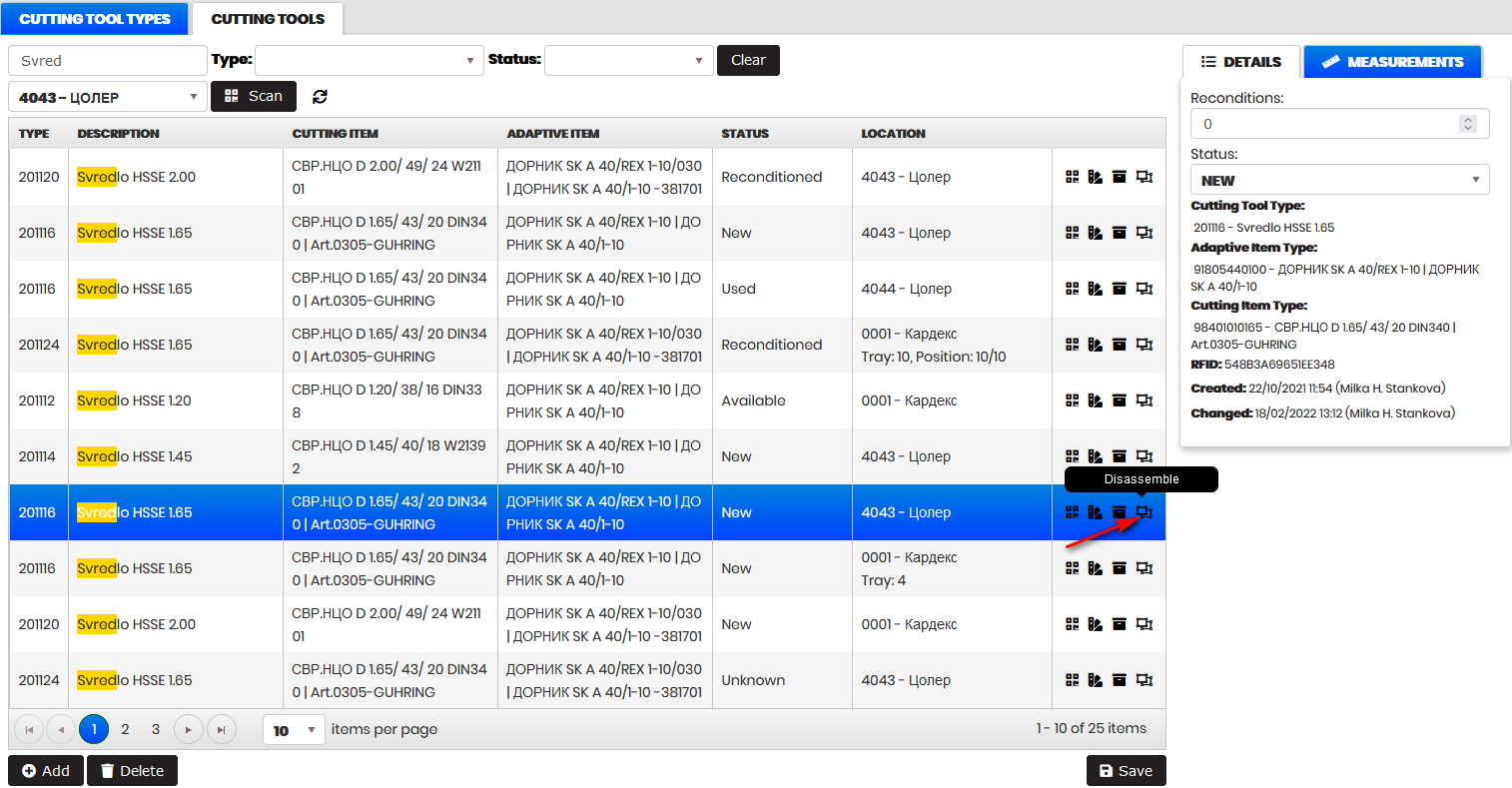
Figure 31: Cutting tools - Open Disassemble form
- Disassemble form opens.
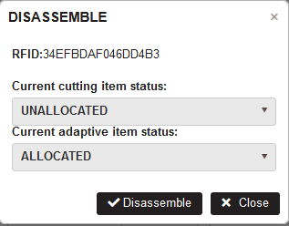
Figure 32: Return the cutting tool to storage
Select the cutting item status and the adaptive item status in the form. The cutting tool is removed from the table.
- The cutting tool is disassembled and removed from the cutting tool table.
Clamping Devices
Purpose: The Clamping devices menu is used to:
- View or create clamping device types and instances.
- Upload and download the drawings attached to clamping device types.
- View attached instances to each type.
- Add or delete clamping devices.
The clamping device types with their drawings are imported from the ERP system or created manually.
The section describes:
Clamping Device Types
Select the menu Tool Management/Clamping devices.
- The Clamping device types page opens.
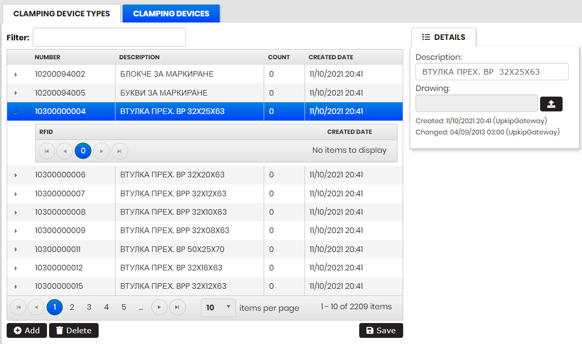
Figure 33: Clamping Devices - Clamping Device types
The table shows clampin device types with number, description, count (number of instances of this type), and created date.
It is possible to filter the clamping device types by entering in the Filter field part of the number or description of the type.
- The table is automatically filtered.
Selecting a row from the table opens Details at the right side with description and attached drawing. It is possible to upload or download the drawing of the type.
Clicking on the arrow at the left side of some row expands the type with the list of instances created with it. Each instance is shown with RFID and created date.
The table can be sorted by all columns clicking on the columns headings.
Click on the Add button.
- Create Clamping device type form opens.
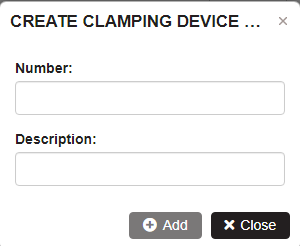
Figure 34: Clamping Devices - Add clamping device type
Enter the number and description and click Add.
- The new clamping device type is added and appears in the table.
Select any line of clamping device type that has no attached instances of clamping devices to it. Click Delete.
- The Clamping device type is deleted and removed from the table.
Select any line of clamping device type with Count greater than zero and click Delete. Confirm.
- A message is displayed „Cannot delete clamping device type. There is 1 clamping device attached to it.“
Clamping Devices
Precondition: Select the menu Clamping Devices/Clamping Devices.
- The Clamping devices page opens.
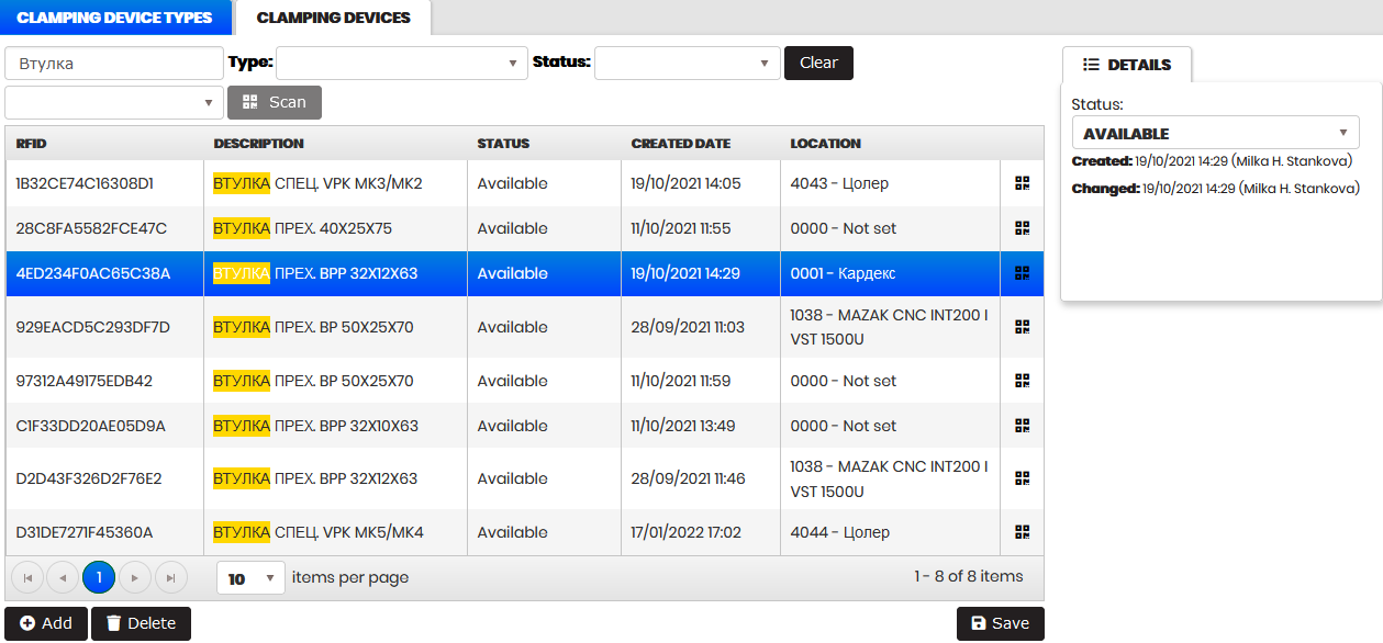
Figure 35: Clamping devices
The table shows the clamping devices with RFID, type, status, created date, location, and icon for changing RFID.
It is possible to filter the clamping devices by entering part of the RFID or type in the Filter field.
- The table is automatically filtered.
Filtering by status is possible from the Status filter. Filtering by type is possible by the Type filter.
To scan the clamping device RFID:
- Select the location from the drop-down list.
- Click the button Scan, and then scan the RFID
- Via push notification, the scanned RFID is sent to the Filter field and the table is filtered. The scanned clamping device is attached to the selected location.
Clicking the Clear button clears all filters and shows the table with all clamping devices.
Selecting a row from the table opens Details on the right side. It is possible to change the clamping device status from the Status dropdown.
The table can be sorted by all columns clicking on the column headings.
Click the Add button.
- Create Clamping device form is opened.
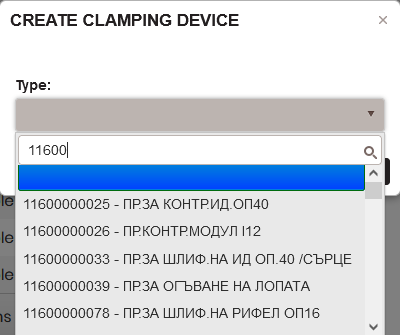
Figure 36: Create clamping device - select clamping device type
Filter the clamping device types by typing in the search field. Select some type from the dropdown.
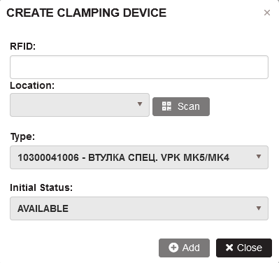
Figure 37: Create clamping device
Select a location and click the Scan button.
Scan the RFID of the clamping device.
- RFID is sent via push notification and filled in the RFID field.
Click the Add button.
- The new clamping device is created and appears in the table.
Select any line of clamping device and click Delete. Confirm.
- The Clamping device is deleted and removed from the table.
Change clamping device RFID
Select a clamping device by clicking on the row. Click the icon Change RFID from the last column.
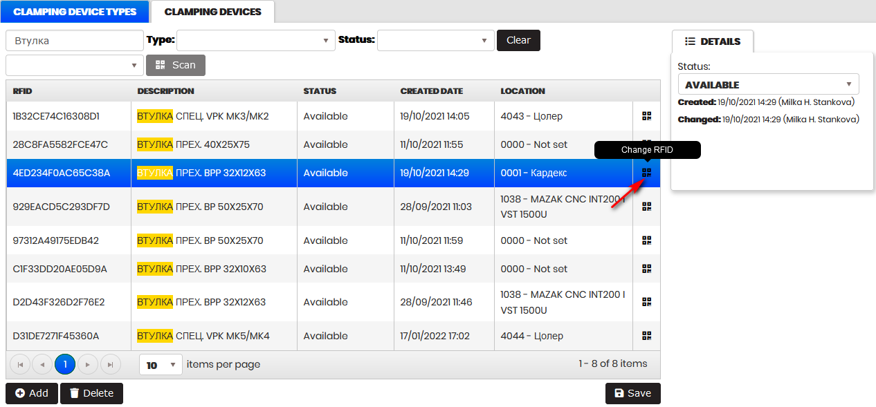
Figure 38: Clamping devices - open the form Change RFID
- The Change RFID form opens.
Figure 39: Change RFID of a clamping device
On first scan, select a current location from the list and click the Scan button. Scan the clamping device.
- The scanned RFID is loaded into the RFID field.
- With a Cardex location selected, it is possible to change RFID without entering tray, column and row.
Click Change RFID button.
- The clamping device gets the new RFID
Selecting a new clamping device and clicking the Change RFID icon, automatically loads the current location with already used ones and selects the Scan button.
Figure 40: Scanning RFID with saved current location
User can scan a clamping device and save by clicking the Change RFID button.
Transfer
Purpose: The Transfer page shows the current location of the cutting tools and clamping devices in real time. It is possible to change the location of selected cutting tools or clamping devices.
Real Time
Select the menu Tool Management/Transfer.
- The Transfer/Real Time page opens.
Purpose: The Real Time page shows the number of cutting tools and the number of clamping devices in place. Clicking on the filters icons open the filtered lists of cutting tools or clamping devices for the machine.
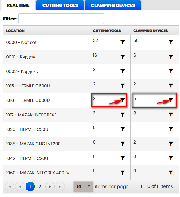
Figure 41: Transfer - Real Time
Clicking the cutting tools filter icon in a row of real-time table opens the cutting tools tab filtered with the relevant cutting tools for the machine.
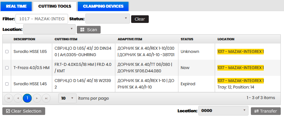
Figure 42: Transfer - filtered cutting tools for machine
Clicking the clamping devices filter icon in a row of real-time table opens the clamping devices tab filtered with the relevant clamping devices for the machine.

Figure 43: Transfer - filtered clamping devices for machine
Typing in the Filter field a machine number filters automatically table.
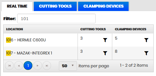
Figure 44: Transfer - Filtering Real Time table
Transfer Cutting Tools
Purpose: The Transfer/Cutting Tools page shows the current locations of the cutting tools. The selected cutting tool(s) can be transferred to the selected location.
Select the menu Tool Management/Transfer/Cutting tools
- The Transfer/Cutting tools page opens.
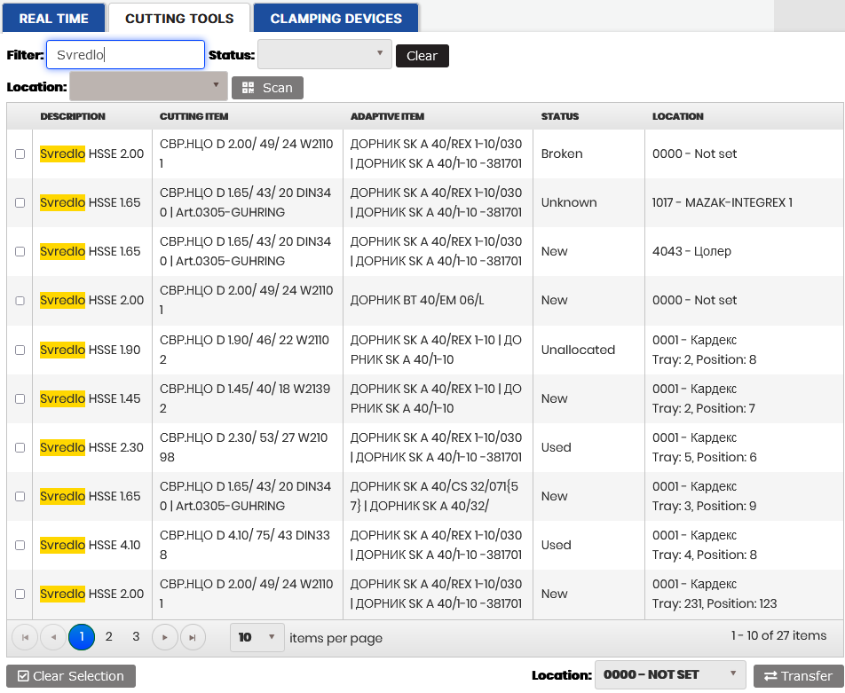
Figure 45: Transfer - Cutting tools
Table lists cutting tools with RFID, type, cutting item number, adaptive item number, status, and location.
To scan the RFID of the cutting tool:
- Select the location from the drop-down list.
- Click the button Scan, and then scan the RFID. Via a push notification, the scanned RFID is sent to the Filter field and the table is filtered. The scanned adaptive item is attached to the selected location.
Filtering the cutting tools table is possible by entering in the Filter field part of the RFID, type, cutting item type or number, adaptive item type or RFID, location.
Changing the locations of cutting tools is possible in steps:
- Select by checkboxes some cutting tools.
- Select a machine from the location drop-down.
- Click the Transfer button.
- The selected cutting tools are transferred to the selected location.
- The location of the cutting tools in the table is updated.
When moving the cutting tool to the Kardex storage, it is necessary to enter the Kardex tray and position.
Transfer Clamping Devices
Purpose: The Transfer/Clamping devices page shows the current locations of the clamping devices. The selected clamping device(s) could be transferred to the selected location.
Select the menu Tool Management/Transfer/Clamping devices
- The Transfer/Clamping devices page opens.
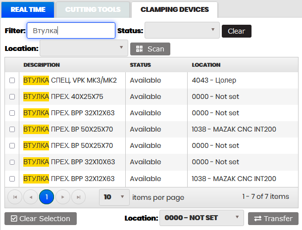
Figure 46: Transfer - Clamping devices
Table shows clamping devices with RFID, type, status, and location.
To scan the RFID of the clamping device:
- Select the location from the drop-down.
- Click the button Scan, and then scan the RFID.
- Via a push notification, the scanned RFID is sent to the Filter field and the table is filtered. The scanned clamping device attaches to the selected location.
Filtering the clamping devices table is possible by typing in the Filter field part of the RFID, type, cutting item type, or location.
Changing locations of some clamping device(s) is possible in steps:
- Select by checkboxes some clamping devices.
- Select a machine from the location drop-down.
- Click the Transfer button.
- The selected clamping device(s) are transferred to the selected location.
- The locations of the clamping devices in the table are updated.
When moving the clamping device to the Kardex storage, it is necessary to enter the Kardex tray and position.
Scanning Heads
Purpose: The Scanning heads page is used to configure machines with Balluff controllers and scan heads. Each Balluff controller has four ports for scanning heads connected to a machine via USB and TCP/IP interface.
Select the menu Tool Management/Scanning Heads
- The Scanning Heads page opens.
The table lists machines with connected controllers, serial ports, and heads.
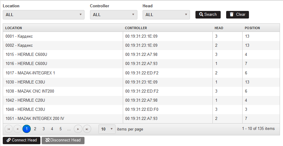 Figure 47: Scanning heads
Machines’ configurations can be filtered by location, controller, or head selected from the dropdown. Click the Search button.
- The table is filtered.
Clicking the Clear button clears the filters and the whole table is shown.
Connect Head
Purpose: The machine is connected to the scanning head via the button Connect head.
Click the Connect Head button.
- Form Connect Head opens.
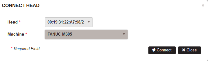
Figure 48: Scanning heads - Connect head
Select a head and machine from the lists and click the Connect button.
- The machine is connected to the head and this appears in the table
Disconnect Head
Purpose: Disconnecting the machine from the head is possible by the Disconnect head button.
Select a row with a connected machine. Click the button Disconnect Head.
- The confirmation popup appears.
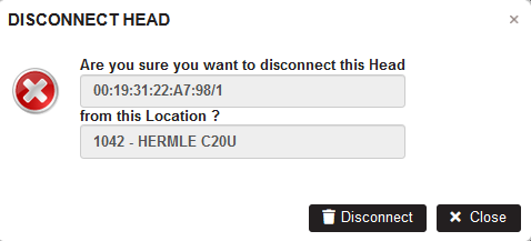
Figure 49: Scanning heads - Disconnect head
Confirm by clicking the Disconnect button.
- The machine is disconnected from the head.
Manage controllers
Purpose: Configure controllers with name, model, mac address and serial port.

Figure 50: Scanners - manage controllers
Click the Manage Controllers button.
- The Manage controllers form opens.
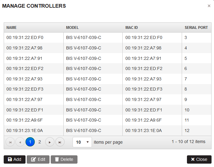
Figure 51: Scanners - manage controllers
Click the Add button.
- The form Add controller opens.
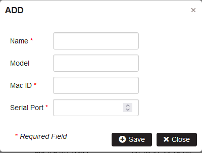
Figure 52: Scanners - add new controller
Enter name, model, mac ID, and serial port. Click Save.
- In the table with controllers is added a new row.
Select the row from the table and click Edit. Make the changes respecting the mac address and serial port uniqueness requirement . Click Save.
- The data for controller are updated.
Select the row from the table and click Delete. Confirm Delete.
- The controller is deleted from the table.